LZZBW-35 Outdoor CT for 35kV Metering
Ratio, 0.2S accuracy, burden and pollution class decide a 35 kV outdoor current transformer. What LZZBW-35 means and how cast resin compares with oil.
Read More

CJ12 contactors are still everywhere. They were built in huge numbers, they are simple, and a maintenance team that has kept them running for twenty years sees no reason to change. But the CJ12 is an air-break device with arc chutes, and in heavy switching duty the arc chutes, the main contacts and the operating coil are exactly the parts that fail. Replacing one with a vacuum contactor of the same current class solves all three problems at once, and the retrofit is a mechanical and control-circuit job rather than an electrical redesign.
This guide sets out how to replace an AC contactor with a vacuum contactor without changing the motor, the protection or the panel drawing more than necessary, including the parts of the job that catch people out: mounting, coil voltage, auxiliary contacts and the overvoltage that a vacuum interrupter produces and an air-break contactor does not. The low-voltage and medium-voltage contactor range is the starting point if you have not yet fixed the frame.
The CJ12 is a double-break air contactor with arc chutes over each pole. Every operation draws an arc that runs up the chute, cools against the splitter plates and is driven out at the top. That design works, and it is why the frame survived so long, but it has three built-in wear paths.
There is also a fourth issue that is not a failure at all: the arc has to go somewhere. A CJ12 needs arc clearance above and around the frame, and it vents hot gas into the cubicle. A vacuum contactor interrupts in a sealed bottle and vents nothing, which changes what the panel can look like.
| Item | CJ12 air-break frame | Vacuum contactor frame |
|---|---|---|
| Arc containment | Open arc in a chute, hot gas vented into the cubicle | Sealed interrupter, no external arc and no vented gas |
| Contact wear mechanism | Continuous erosion, inspected by eye | Very slow erosion, judged by contact resistance and a wear mark |
| Operating noise | Audible hum at twice line frequency plus closing clatter | Near silent while held |
| Panel volume | Arc clearance above and around each pole | Clearance set by insulation only, so the frame is smaller |
| Endurance in AC-4 | Low, and the limit is contact erosion | Published in hundreds of thousands of operations on the larger frames |
| Overvoltage on opening | Low, because the arc limits the rate of current change | Present, because the current is chopped, and needs mitigation |
| Dust and humidity | Contacts exposed to the panel atmosphere | Contacts sealed inside the bottle |
The last two rows are the honest trade. A vacuum contactor brings a fast, clean interruption and pays for it with a steeper voltage transient at the load terminals. That is manageable, and it is covered further down.
The current classes do not map one to one, because the two families were designed to different conventions. A CJ12-100 is rated 100 A in AC-3, while a vacuum frame is rated by its continuous thermal current and its AC-3 and AC-4 duty separately. The mapping below is the practical starting point for a motor starter retrofit, and it always needs checking against the actual motor full-load current and starting duty.
| Existing CJ12 | Typical vacuum replacement | Notes |
|---|---|---|
| CJ12-100 (380/660 V) | CKJ5 250 A frame or equivalent | Vacuum frames start at a higher current class, so the replacement is usually one size up |
| CJ12-150 (380/660 V) | CKJ5 250 A or CKJ20 250 A | Choose on AC-4 duty if the load is a hoist, crusher or mill drive |
| CJ12-250 (380/660 V) | CKJ20 400 A or 630 A | Check the cubicle depth; the horizontal CKJ5 fits shallow drawers |
| Heavy duty above 630 A at 1,140 V | GKJ5 1000 A or 1250 A vertical frame | Vertical column suits tall cubicles; three-pole and single-pole versions |
The CKJ5 horizontal vacuum contactor covers 380 V, 660 V and 1,140 V at 250 A, 400 A and 600 A with the interrupter axis laid sideways, which is what allows it to drop into a shallow drawer where a vertical frame will not fit. The CKJ20 frame goes to 800 A at 660 V and 1,140 V with three million mechanical operations, and the GKJ5 vertical three-pole frame covers the 1,000 A and 1,250 A class used on mill and mine duty.
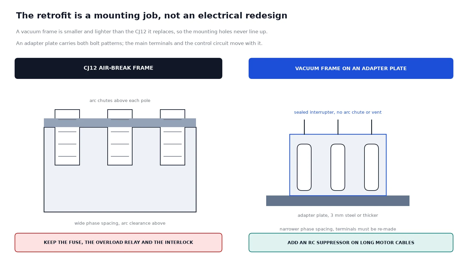
A vacuum contactor is smaller and lighter than the CJ12 it replaces, so the mounting holes never line up. The standard solution is a steel adapter plate drilled for the old frame on one side and the new frame on the other, with the plate stiff enough not to flex. A flexing plate changes the contact gap as the frame operates, and a contact gap that closes short is how a vacuum bottle gets destroyed.
Three mechanical rules apply to every retrofit.
A CJ12 is operated by an AC magnet with coil options of 36 V, 127 V, 220 V or 380 V AC, and the panel’s control transformer is tapped to suit. Most vacuum contactors in this class are offered with the same AC coil voltages, but the coil inside is a DC magnet fed through a rectifier bridge with a current-limiting resistor switched in after pull-in. That design is why the vacuum unit is silent when held and why its holding current is a fraction of the air-break frame’s.
For the retrofit this means the control voltage can usually stay exactly as it is, provided the new coil is ordered for that voltage. It also means four items must be checked before the panel is re-energised.
The coil voltage and control wiring guide covers the terminal-level detail, including pick-up and hold values and the sizing of the control fuse.
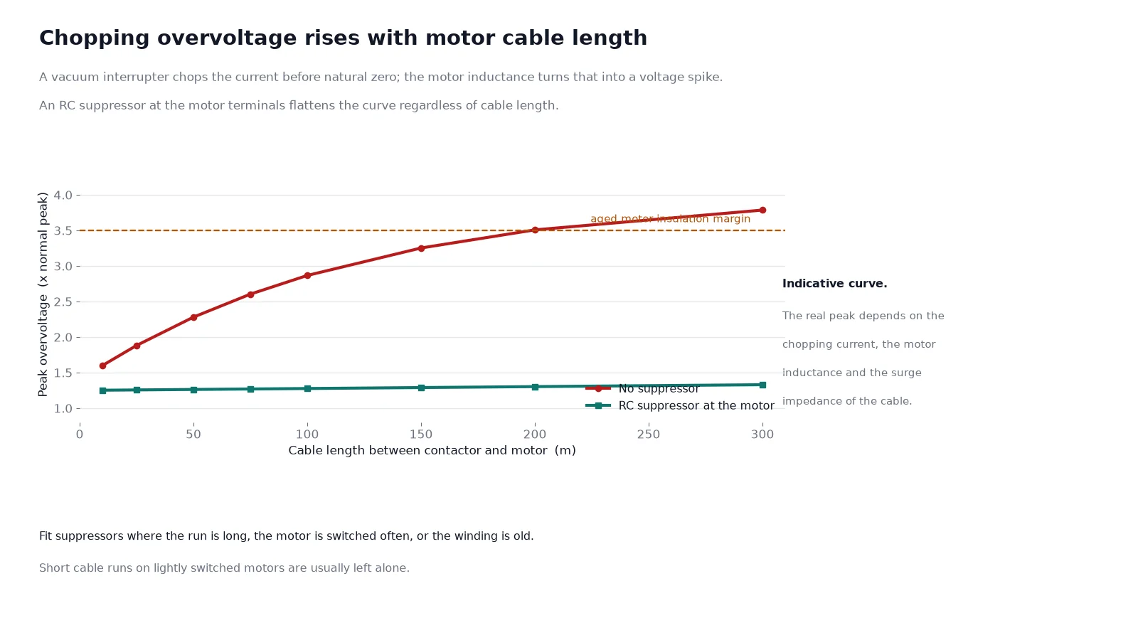
An air-break contactor’s arc continues until the current reaches a natural zero, so the inductive load is discharged gradually. A vacuum interrupter chops the current before that zero, and in a motor circuit the chopped current interacts with the motor inductance to produce a voltage spike. The magnitude depends on the motor, the cable length and the chopping current of the interrupter, and it is worst with long cable runs and with motors that are switched frequently.
Two mitigations are standard. Fit an RC suppressor at the motor terminals, sized for the motor, which damps the transient at its source. Or fit a surge arrester at the motor or at the contactor load terminals, which clamps the peak. On a large retrofit programme the cheapest approach is to fit suppressors only on the long-cable and high-switching-frequency drives and leave short-cable, lightly switched motors alone.
A contactor is a switching device, not a protective device. It has no short-circuit rating in the sense a breaker has, and it must remain downstream of a fuse or a moulded-case breaker that clears the fault. Swapping a CJ12 for a vacuum frame does not change that, and a retrofit that removes the fuse because “the contactor is now sealed” is dangerous.
Three items must stay in the circuit: the short-circuit protective device ahead of the contactor, the thermal overload relay (or the electronic equivalent) set to the motor’s service factor current, and the isolator or interlock that lets a person work on the motor safely. The vacuum contactor’s job is only to switch.
Step 12 is worth keeping as a habit. A coil current that drifts upward over the following months points to a rectifier diode or a resistor that is failing, and it gives the maintenance team a warning that the CJ12 never offered.
If the existing panel has no space for the adapter plate and no way to re-make the cable terminations, a like-for-like CJ12 replacement is cheaper than a panel rebuild. If the drive is a soft-starter or a variable-frequency drive, the contactor only switches at start and stop and the CJ12’s arc duty is trivial, so the case for replacement is weak. And if the fault level at the panel exceeds what the existing fuse can clear, the problem is the protection, not the contactor, and it should be fixed first.
Electrically it is a straightforward replacement in the same current class. Mechanically it is not: the mounting pattern, the terminal spacing and the auxiliary contact arrangement all differ, so an adapter plate and a control circuit rewire are part of the job.
Usually yes. Order the vacuum contactor with a coil for the existing control voltage, and specify whether the panel’s supply is AC or DC. If a DC coil is ordered without a DC source, the panel needs a rectifier.
It does not cause the failure, but vacuum interruption produces a steeper transient than an air-break arc did, and aged motor insulation can be the part that gives way. Fit an RC suppressor or an arrester at the motor terminals on long cable runs.
No. A contactor switches; it does not clear a short circuit. The fuse or breaker ahead of it must stay, and the overload relay downstream of it must stay as well.
Published figures for the larger frames run to three million mechanical operations and tens of thousands of AC-4 electrical operations, which is several times the air-break frame in the same duty. The limitation moves from contact erosion to the vacuum bottle and the coil, both of which are monitored rather than inspected by eye.
Only if its setting range does not cover the motor current. The relay itself is independent of the contactor, and keeping it preserves the existing protection coordination.
If you can supply the existing frame model, the motor full-load current, the duty and the control voltage, the replacement frame and its adapter arrangement can be fixed in one exchange. Send photographs of the installed contactor with the enquiry, including the coil label, and the coil and auxiliary block will arrive matched to the panel instead of needing a second order. The introduction to how a vacuum contactor works explains why the sealed bottle behaves differently from an arc chute if the maintenance team needs the background. Send the nameplate photographs to our engineers and the substitution is confirmed before the order.