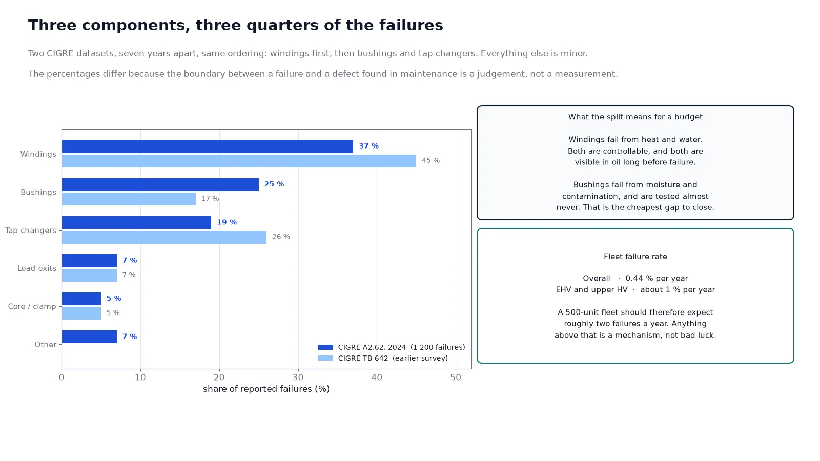
Ask a maintenance engineer what kills transformers and the answer will usually be a story: a lightning strike, a rat, a loose lug. Ask the reliability data and the answer is less dramatic. Recent surveys of more than a thousand failures put roughly three quarters of them in three components — windings, bushings and tap changers — and most of those begin as a slow thermal or moisture process that ran unobserved for years.
That gap between the anecdote and the statistics matters, because it decides where a prevention budget goes. A transformer failure causes analysis is only useful if it tells you which mechanisms you can actually influence, and in what order.
What the failure statistics actually say
CIGRE’s 2024 reliability work (A2.62) analysed more than 1,200 transformer failures reported by 66 utilities across 27 countries. Windings accounted for 37 %, bushings 25 % and tap changers 19 %. The earlier CIGRE Brochure 642 dataset gave a similar split — windings 45 %, tap changers 26 %, bushings 17 %, lead exits 7 % — and put the overall annual failure rate at about 0.44 %, rising to around 1 % at the top of the high-voltage range.
| Component |
Share of failures |
Dominant mechanism |
Detectable before failure by |
| Windings |
37–45 % |
Thermal ageing of paper, then dielectric breakdown under a through-fault |
Furan, CO and CO2 in DGA, winding resistance, turns ratio, SFRA |
| Bushings |
17–25 % |
Moisture ingress, partial discharge, surface contamination |
Power factor and capacitance, thermography, visual inspection |
| Tap changers |
19–26 % |
Contact wear, carbonised oil, drive failure |
Compartment DGA, motor current, operation count |
| Core and clamping |
5–10 % |
Interlaminar short, loose clamp, multiple earth |
No-load loss, excitation current, acoustic signature |
| Lead exits and connections |
~7 % |
Loose joint, poor brazing, thermal cycling |
Thermography, contact resistance |
The percentages vary between datasets because the boundary between a “failure” and a “defect found during maintenance” is a judgement. The stable message is the ordering: windings dominate, and windings fail because of heat and water, not because of manufacturing defects.
Cause one: thermal ageing of the paper
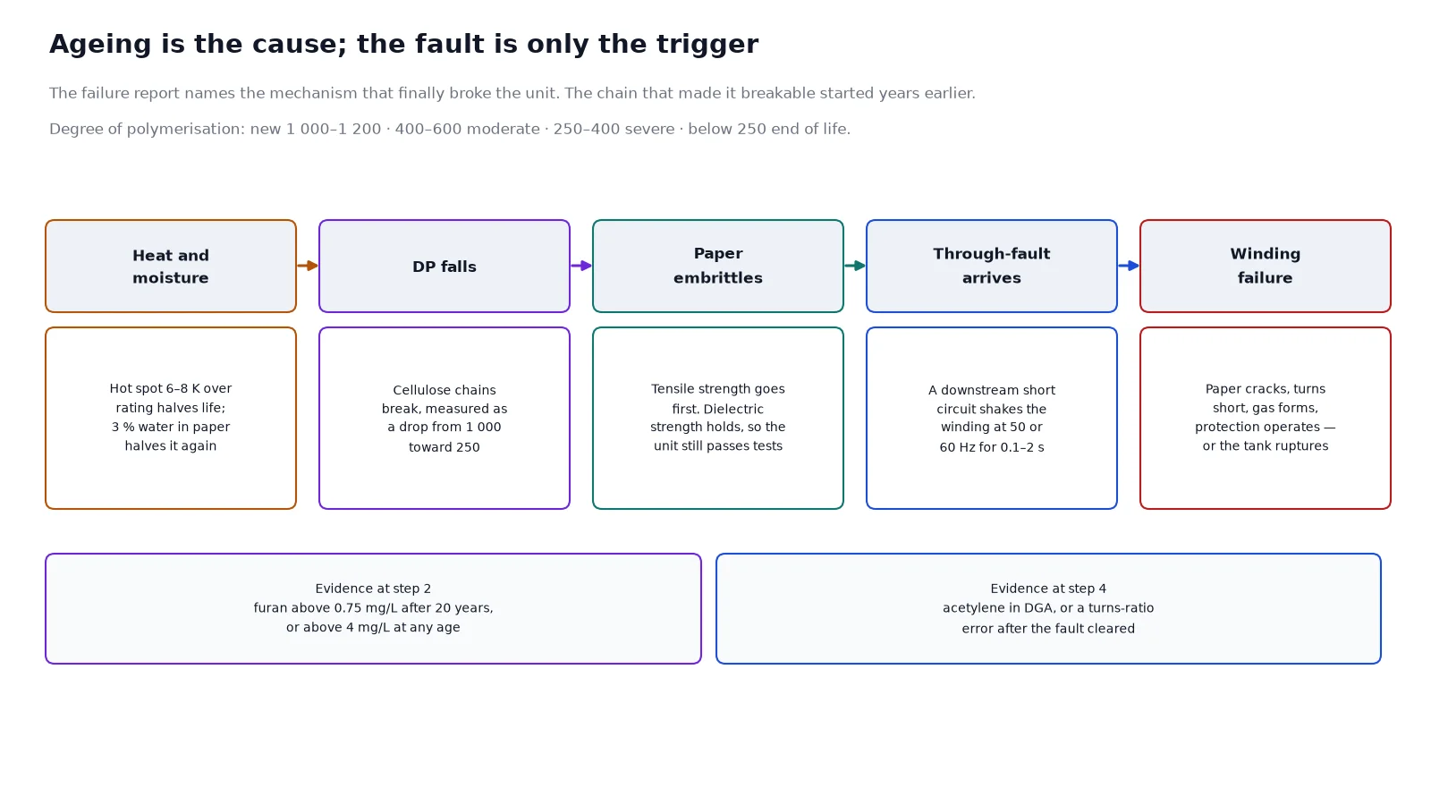
The copper and the core will outlive everyone involved. What limits the transformer is the cellulose paper wrapped around the conductors, and it degrades by a chemical reaction whose rate roughly doubles for every 6 to 8 K that the hot spot runs above its rated temperature. This is the classic eight-degree rule, and its practical consequence is unpleasant: running 10 K hot does not cost a few percent of life, it costs approximately half of it.
Heat comes from four places, and only one of them is the load:
- Sustained overload. The obvious one, and the easiest to see on a load chart.
- Blocked cooling. Dust on radiator fins, a closed plant-room louvre, a failed fan stage, a recirculating hot-air pocket. This is the most common avoidable cause, because nothing alarms.
- Harmonic current. Non-linear loads push eddy-current and stray losses up faster than the fundamental current suggests, so a unit at 85 % of nameplate current can be at 110 % of its thermal duty. Our note on K-factor and harmonic derating quantifies it.
- High ambient. A transformer rated at 40 °C installed in a 48 °C roof plant room is derated whether or not anyone recalculated.
The consequence chain is always the same. Heat embrittles the paper; embrittled paper loses mechanical strength; a through-fault — a downstream short circuit — shakes the winding, the paper cracks, and the winding fails electrically. This is why an aged transformer often appears to die from a fault it should have survived: the fault was the trigger, the ageing was the cause.
Cause two: moisture
Water is the multiplier on everything above. A 1.5 % moisture content in paper is normal service condition; at 3 % the mechanical life is roughly halved at the same temperature, and the dielectric strength of the oil falls with it. Moisture also lowers the temperature at which gas bubbles form, which is the mechanism behind failures that occur at apparently normal loading.
It gets in through five routes: a saturated or empty breather oil seal, a weeping gasket, a badly executed oil top-up from an unsealed drum, an open terminal box on a humid night, and paper ageing itself — because the degradation reaction produces water as a product, which then accelerates the reaction. The last one is why an old transformer ages faster than its temperature alone would predict.
For a dry-type unit the mechanism changes but the effect does not: moisture plus dust on a resin surface creates a tracking path, and condensation inside an enclosure without anti-condensation heaters does the same job more slowly. Enclosure IP rating decides how much of that exposure the unit sees, but no IP rating substitutes for a heater and a drain. On an oil-immersed unit, the water is visible in the oil long before it reaches the paper, which is why sampling intervals belong in a written maintenance schedule rather than in a habit.
Cause three: bushings
Bushings fail differently from windings. They are a small, highly stressed component with a porcelain or composite shed, a condenser core, and a joint at each end, and the failure is usually a flashover or a mechanical break rather than a slow thermal decline. The precursor is moisture in the core — invisible from outside and measurable only by power factor and capacitance — or contamination on the surface.
Three environmental conditions drive it: coastal salt, cement and fertiliser dust, and any atmosphere that deposits a conductive film. A bushing that tracks in the rain at 40 % of its dry flashover voltage is doing exactly what a contaminated surface does. Cleaning intervals belong in the maintenance schedule for those sites, and thermography catches the other mode — a hot terminal connection — before it burns through.
Cause four: tap changers
On-load tap changers are the only components in a transformer that move on purpose, and they carry the maintenance burden that implies. Contact wear, carbonised diverter oil, a motor drive that loses torque, and a mechanism that sits unused for years and seizes when called upon. Off-circuit tap changers fail in the opposite way: they are so rarely operated that a resistive film forms on the contacts and the first operation under load destroys them.
The practical prevention is unglamorous. Exercise the off-circuit changer through its full range once a year, de-energised. Sample the diverter compartment separately, because its oil degrades far faster than the main tank and mixing the results hides the trend. Log the operation count.
Cause five: core and stray flux
Core faults are rarer but distinctive. An interlaminar short from a burr or a damaged edge produces a local hot spot and a rising no-load loss; a loose clamping structure produces a buzzing that changes with load; a second earth on the core produces a circulating current that overheats the frame. None of these announce themselves electrically at first — they show up in no-load loss measurements, in acoustic signature, and eventually in gas.
Stray flux is the related problem in high-current LV windings: flux leaking outside the core induces eddy currents in the tank wall, the clamping frame and the busbar supports, and the resulting local heating is invisible until thermography finds it. Units with high harmonic content or unbalanced loading are the usual candidates.
Cause six: through-faults, surges and switching
A transformer is designed to withstand a short circuit at its terminals for a defined time — typically 2 s thermally, with the mechanical withstand demonstrated by a type test. What it is not designed to do is absorb repeated through-faults late in life with brittle paper. Each event moves the winding, and cumulative movement is what turns a survivable fault into a failure.
Surges arrive by two routes. Lightning on the incoming overhead line is the familiar one, and it is a surge arrester problem as much as a transformer problem — the arrester selection and its lead length decide the residual voltage the winding sees. Switching surges and resonance from capacitor bank operations are the second route, and they are more common on cable-heavy medium-voltage systems than most operators expect. Our note on surge arresters for 10 kV distribution covers the co-ordination, and the withstand side is set out in our guide to impedance and short-circuit duty.
Cause seven: workmanship and connections
A meaningful share of failures are installed, not manufactured. A joint torqued to feel rather than to specification; a cable lug crimped with the wrong die; a busbar support that leaves a clearance below the minimum; a core earth strap left disconnected at one end and doubled at the other. These are found by inspection at commissioning, which is why a documented commissioning routine earns its cost. The checks and their acceptance values are listed in our pre-commissioning checklist.
Cause eight: the environment
Corrosion of the tank, ingress through a failed gasket, vermin in an open terminal box, vegetation against a radiator, a drain that blocks and floods the plinth. On a dry-type unit, the equivalent is dust bridging creepage paths and resin cracking under thermal cycling, which is where partial discharge begins. A cast-resin unit with rising PD is not a unit to keep in service while a spare is ordered — the mechanism is partial discharge in cast resin, and it progresses.
What actually prevents failures
| Mechanism |
Prevention that works |
Prevention that does not |
| Thermal ageing |
Keep the hot spot inside rating; record load and top-oil temperature together |
Periodic visual inspection |
| Moisture |
Breather maintenance, gasket renewal, sealed oil handling, drying before energisation |
Topping up from an open drum |
| Bushing failure |
Power factor and capacitance trend, thermography, cleaning interval in contaminated sites |
Wiping the sheds at each visit |
| Tap changer |
Annual exercise, separate compartment sampling, operation count |
Leaving it in one position for twenty years |
| Through-fault damage |
Correct protection settings, fault level review after network changes |
Assuming the original settings still apply |
| Surge damage |
Arrester co-ordination, short direct leads, single earth reference |
Adding an arrester without checking MCOV against earthing |
| Workmanship |
Torque log, commissioning test set, third-party witness |
Accepting a verbal assurance |
Frequently asked questions
What is the most common cause of transformer failure?
Winding failure, at roughly 37–45 % of reported failures in CIGRE surveys. It is almost always the end point of thermal ageing of the paper insulation, often triggered by a through-fault that the aged winding could no longer withstand mechanically.
How does overheating damage a transformer?
Heat breaks the cellulose polymer chains in the paper, which is measured as a fall in degree of polymerisation. The paper loses tensile strength before it loses dielectric strength, so the unit keeps working while becoming mechanically fragile — and then fails on the first fault that shakes the winding.
Can a transformer fail from moisture alone?
Yes. Moisture reduces the dielectric strength of the oil and the paper, and it lowers the temperature at which water vapour bubbles form. A unit at high moisture can flash over at normal operating temperature, with no fault current and no overload beforehand.
Why do transformers fail after a short circuit nearby?
Because the through-fault current produces mechanical forces proportional to the square of the current, and they move the winding. In a healthy unit the bracing absorbs it; in an aged unit with embrittled paper the insulation cracks and the next fault finds the gap.
Do harmonics really cause transformer failures?
They accelerate them. Harmonic currents increase eddy and stray losses disproportionately, raising the hot-spot temperature beyond what the RMS current suggests. A unit that looks lightly loaded can be thermally at its limit, and the failure is then recorded as thermal ageing rather than as a harmonic problem.
How can I tell whether to repair or replace a failed transformer?
By the condition of the paper rather than the extent of the damage. A winding fault in a unit with healthy insulation and a low furan level is a repair candidate; the same fault in a unit at DP 250 is a replacement, because the repaired winding will be surrounded by insulation that is already spent.
The takeaway
Eight mechanisms, one pattern: the transformer announces almost all of them in oil, in temperature and in sound, months or years before it stops working. The three components that dominate the statistics — windings, bushings, tap changers — are all inspectable and all measurable. What separates a 40-year asset from a 15-year one is rarely the design; it is whether anyone read the numbers.
If you are trying to establish why a unit failed, or to decide whether a fleet is at risk, send us the rating, the age, the last DGA result and the load profile. We will tell you which of these mechanisms fits the evidence, and whether a repair, a derating or a replacement is the defensible answer.