Most CT and PT problems in a 12 kV switchroom are not failures. They are mismatches that were built in at the quotation stage: a current transformer with the right ratio but the wrong core, a voltage transformer wired in V-V when the protection scheme expects an open delta, a lead run long enough to consume the whole rated burden. The devices pass their factory tests and then sit there producing a 3% metering error or a protection trip that nobody can explain.
This guide is about the matching work itself, for the two cabinets that cause most of it: the KYN28 metal-clad cubicle and the ring main unit. Both are 12 kV indoor equipment. They ask for completely different instrument transformers for switchgear, and that difference is where the mistakes come from.
Two cabinets, two different questions
A KYN28 cubicle is a metal-clad, withdrawable assembly with separate busbar, breaker and cable compartments. There is room, there is a defined CT mounting position behind the breaker, and the PT sits on the busbar side of the main disconnector so it can be isolated for maintenance. A ring main unit is a sealed, compact assembly. The current transformers are usually window-type rings slipped over the cable cores, the voltage transformer is a small cast block in a corner of the tank, and there is no space to add a second core later.
That physical difference drives every downstream choice.
| Question |
KYN28 cubicle |
Ring main unit |
| CT mounting |
Pillar-type, bolted to the cable compartment floor or breaker frame |
Ring / window type over the cable core, or a combined metering block |
| CT ratio freedom |
Free — any ratio in the frame’s matrix |
Limited by cable diameter and the ring aperture |
| PT arrangement |
Two or three single-phase units, or a three-phase set, on a withdrawable truck |
Two or three small cast units, often combined with the CTs in one block |
| Residual voltage winding |
Easily added — a third core or a broken-delta winding |
Must be ordered with the unit; cannot be retrofitted |
| Burden headroom |
Ample — a 10 or 15 VA core is normal, 20–30 VA available |
Tight — the metering core is often 10 VA and shared |
| Typical weak point |
Wiring between compartment and relay panel |
Ratio fixed too early, before cable size was known |
Start with the switchgear rating, not the load
A current transformer has to survive the fault current the cubicle can deliver, not the current the load draws. This is the first number to fix, and it comes straight off the switchgear nameplate: 12 kV, 630 to 3150 A busbar, 20 to 40 kA short-time withstand for 4 s, 63 to 100 kA peak, 42 kV power frequency for one minute and 75 kV lightning impulse on common 12 kV builds.
The CT’s one-second thermal current and rated dynamic current must be at or above those values. In the LZZBJ9-10 frame the two numbers scale in steps rather than smoothly: 150 A primary gives 22.5 kA thermal and 44 kA dynamic, the 400–600 A rows give 45 kA and 90 kA, and the 800–1 000 A rows give 63 kA and 100 kA. A frame chosen only on ratio can therefore end up under-rated on fault duty while looking perfectly correct on the datasheet.
The same logic sets the frame size. Once a feeder goes above 1 000 A, the pillar CT that fitted the 630 A cubicle is no longer in its matrix, and the specification moves to a larger frame. If you are matching instruments for a new cubicle rather than replacing one, read the KYN28 installation sequence first — the CT is installed before the breaker is racked in, and the wiring route is decided at the same time.
CT ratio: where the 1.2 to 1.5 rule actually comes from
For a plain feeder, the rule is simple: the CT primary rating is at least the circuit’s continuous rating, and the meter should normally sit between 20% and 100% of that rating. Below about 20% the accuracy class no longer holds, because the error limits are defined at 5%, 20% and 100–120% of rated current.
For a motor circuit the rule tightens to 1.2–1.5 times the motor full-load current. That factor is not margin for taste. It exists so the CT is not sitting at 100% on a motor that runs slightly above nameplate, and so the protection core still has headroom when the motor starts at five to seven times FLA.
| Feeder rating |
CT ratio |
Typical core set |
What to watch |
| 200 A |
200/5 or 300/5 |
0.5 metering + 5P10 |
Light loads fall below 20% and the class lapses |
| 400 A |
400/5 |
0.5 or 0.2S + 5P10 |
Confirm the 1 s thermal against the busbar rating |
| 630 A |
600/5 |
0.5 + 5P10 or 5P20 |
The most common cabinet; check dynamic current at 90 kA |
| 1 250 A |
1 200/5 |
0.2S + 5P20 |
Above the LZZBJ9-10 matrix — frame changes |
| 2 000 A and above |
2 000/5 |
0.2S + 5P20 or 10P20 |
Secondary lead burden becomes the limit, not the CT |
The CT ratio selection table goes further into how the ratio interacts with the meter constant, but the mechanical rule above covers the switchgear case.
One CT body, two cores, two jobs
A protection-and-metering CT is not one transformer. It is two or three cores inside a single cast body, each with its own accuracy specification. The metering core carries 0.2, 0.5, 0.2S or 0.5S, and its job is to be accurate at normal current. The protection core carries 5P10, 5P20 or 10P20, and its job is to stay honest during a fault.
The suffix on the protection class is the accuracy limit factor: 5P10 means the composite error stays within 5% up to ten times rated primary current. A 5P20 core holds that error to twenty times, which is what a feeder with a high fault level relative to its rating needs. Selecting 5P10 on a 630 A feeder with 25 kA of fault current is a mismatch in the arithmetic — the fault is nearly forty times rating, well past the core’s declared limit.
The metering side has its own trap. Classes 0.2S and 0.5S hold accuracy from 1% of rated current rather than 5%, which matters for a feeder that runs lightly loaded at night. A standard 0.5 class unit on the same feeder will drift outside its error band at low load, and the revenue meter will show a small but persistent bias.
For KYN28 work the usual builds are the LZZBJ9-10 pillar CT for standard cubicles and the LZZBJ12-10 where the secondary terminals need shielding against tampering in a humid switchroom. Both are 10 kV indoor frames with a metering core and a protection core as standard.
The PT ratio is a connection decision before it is a ratio decision
Buyers ask for 10/0.1 kV and assume the job is done. It is not, because the same primary voltage produces three different secondary values depending on how the three units are connected.
| Connection |
Units |
Ratio |
Measures |
Used for |
| V-V (open delta) |
2 |
10/0.1 kV |
Line-to-line voltage |
Metering only, no earth-fault detection |
| Y-Y, star |
3 |
10/√3 / 0.1/√3 kV |
Phase-to-earth voltage |
Three-phase metering and relays |
| Y-Y with broken delta |
3 |
10/√3 / 0.1/√3 / 0.1/3 kV |
Phase voltage plus residual |
Insulation monitoring in an unearthed network |
| Combined metering block |
2 or 3 PT + 2 or 3 CT |
10/0.1 kV |
Voltage and current in one casting |
RMU billing points |
The broken-delta case is the one that gets lost between the switchgear supplier and the protection supplier. The residual winding produces about 100 V across the open delta during a solid single-phase earth fault, and the relay is typically set to operate between 80 and 100 V. If the PT was ordered without that winding, there is no residual voltage and the earth-fault element has nothing to work with — the cabinet is complete, the relay is healthy, and the protection simply cannot see the fault.
On the primary side, a fused unit is the right answer wherever the voltage tap has no upstream protection of its own. The JDZX18 fused cast PT carries its primary fuse inside the same epoxy body for 6 kV and 10 kV indoor duty, which removes a separate fuse holder and the wiring between them. The fuse rating itself has to be coordinated with the winding, not chosen by habit — that problem is covered separately in PT fuse selection.
Burden is the number that gets copied, not calculated
A CT rated at 10 VA does not deliver 10 VA to the relay. The rated output is the total secondary burden at which the accuracy class still holds, and the lead resistance is part of that total. This is the single most common matching error in a 12 kV switchroom, because the lead run between the cable compartment and the relay panel is rarely drawn on the schematic as an electrical quantity.
The arithmetic is unforgiving at 5 A secondary. Burden in VA equals 25 times the total loop resistance in ohms, so every 0.1 Ω of lead costs 2.5 VA.
| Lead cross-section |
Loop resistance, 50 m |
Burden at 5 A |
Left for the relay from a 10 VA core |
| 2.5 mm² |
0.35 Ω |
8.8 VA |
1.2 VA — not enough for a digital relay plus contacts |
| 4 mm² |
0.22 Ω |
5.5 VA |
4.5 VA — workable, tight |
| 6 mm² |
0.15 Ω |
3.6 VA |
6.4 VA — comfortable |
| 10 mm² |
0.09 Ω |
2.2 VA |
7.8 VA — headroom for a second device |
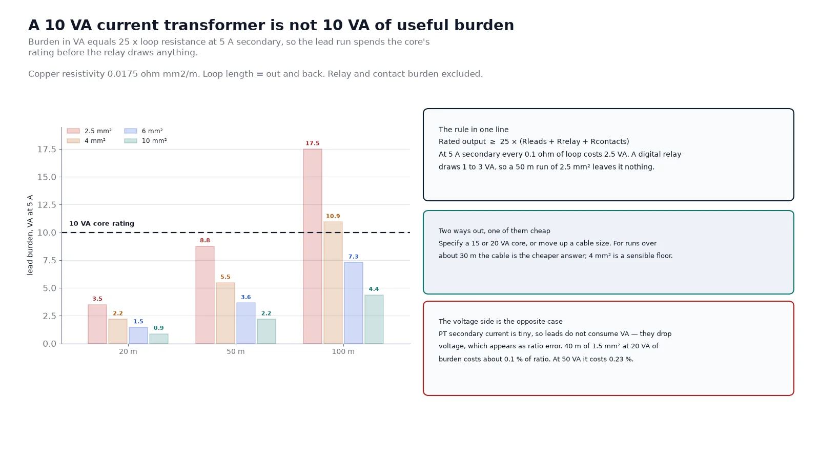
The chart makes the trade-off visible: at 100 m even 6 mm² leaves less than half the core for the relay, which is why long CT runs in a large switchroom end up specified at 20 VA rather than 10 VA.
Two ways out exist. Specify a 15 or 20 VA core, or increase the lead cross-section. In practice the cable is cheaper than the wider core, and 4 mm² should be the floor for any CT circuit longer than about 30 m. A 2.5 mm² run at 50 m already consumes most of a 10 VA core before the relay draws anything.
The voltage side behaves differently, and this asymmetry is worth remembering. PT secondary current is tiny — a 20 VA burden at 100 V draws 0.2 A — so the leads do not consume significant VA. What they do instead is drop voltage, which shows up directly as a ratio error. A 40 m loop of 1.5 mm² has about 0.47 Ω, which produces roughly 0.09 V of drop at 0.2 A, or about 0.1% of ratio error. Push the burden to 50 VA and the same leads give 0.23%, which is nearly half the 0.5 class allowance spent on cable.
What a ring main unit changes
An RMU has no room for a second chance. The ring switches, the tee-off and the metering point sit in one sealed enclosure, and the current transformers are window rings around the cable cores. Their ratio is fixed by the cable that was pulled, and the aperture limits how large a core can be. Specifying 600/5 before the cable schedule is issued is how a unit ends up with a 400/5 ring because the 630 A cable would not pass through the 600/5 aperture.
The practical answer in compact units is a combined metering block: two or three voltage transformers and two or three current transformers cast into one body, sharing a single primary connection. A 10 kV combined unit typically offers 0.2S or 0.5S accuracy, a 10 000/100 V voltage ratio, primary currents from 5 to 400 A, 20 VA on the voltage side and 10 to 20 VA on the current side, with 100 times rated current for one second thermal and 250 times dynamic. It is a billing device, so it is ordered against the utility’s metering requirement rather than against the load.
Two things to check before ordering one. First, whether the utility wants two-element (V-V plus two CTs, three-phase three-wire) or three-element (three PTs plus three CTs, three-phase four-wire) metering — the two are not interchangeable and the meter type follows. Second, the creepage distance: 340 mm is a common figure for a 10 kV outdoor casting, and it should be stated with the pollution level, not assumed.
The matching checklist
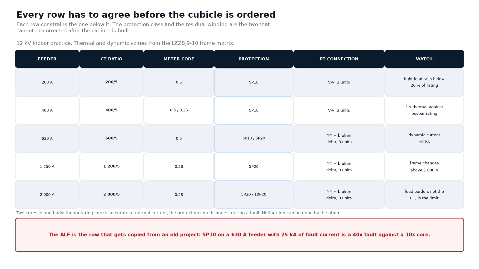
Work down the list in order. Each row constrains the one below it, and the two rows that cannot be corrected after the cabinet is built are the protection class and the residual winding.
- Fault duty before ratio. CT one-second thermal and dynamic current at or above the switchgear’s short-time and peak withstand.
- Ratio against continuous current. At least the circuit rating; 1.2–1.5 times full-load current for motor circuits.
- Core count. One metering core plus one protection core minimum. Two protection cores if the scheme has both overcurrent and differential.
- Class split. 0.5 or 0.2S for metering, 5P10 or 5P20 for protection. The ALF must cover the fault-to-rating ratio.
- PT connection. Decide V-V, star or broken delta from the protection scheme, not from habit.
- Residual winding. Required in any unearthed network with earth-fault detection. Cannot be added later.
- Burden with leads. Total VA including the lead loop, and the lead cross-section that makes it work.
- Secondary earthing. One point only, at the CT star point or the relay panel — never both.
Commissioning checks that catch a mismatch
Four tests find almost every matching error before the cubicle is energised. A ratio test on each core confirms the nameplate against the actual winding. A polarity check confirms that the metering and protection cores agree on direction, which matters the moment a directional element is involved. A secondary loop resistance measurement confirms the lead burden the CT will actually see. And an insulation resistance test on the secondary wiring catches the earth fault that would otherwise short out a core.
The instrument transformer testing sequence covers the full set, including the composite error check that confirms the protection core still meets its class at the accuracy limit factor.
What to fix first if you inherited a mismatched cabinet
If the cabinet is already built, work in order of consequence. A missing residual winding is a protection gap and cannot be solved in the field — it needs a PT change. A burden overload is usually solvable by re-cabling. A protection core with too low an ALF shows up as a relay that under-reaches on close-in faults, and the fix is a core change at the next outage, not a relay setting change.
A metering error of a few tenths of a percent, on the other hand, is often just the lead run and the class, and it is worth measuring before anything is replaced. Utilities tend to accept a 0.5 class billing point that reads 0.3% high; they do not accept one that reads 3% low, and the difference between those two outcomes is usually a cable size and a core rating chosen on the same afternoon.
If you are specifying instruments for a new 12 kV lineup, the matched set matters more than any single device. The switchgear and substation solutions page sets out how the CT, PT and cubicle are quoted together, and it is the right place to start before the ratio table gets filled in.
FAQ
What ratio CT should I use for a 630 A KYN28 feeder?
600/5 is the standard answer, because the CT primary should be at least the circuit rating and 630/5 is not a catalogue row. Use 0.5 or 0.2S for metering and 5P10 or 5P20 for protection, and confirm the one-second thermal current against the cubicle’s short-time withstand — 45 kA in the LZZBJ9-10 400–600 A rows.
Can one CT serve both metering and protection?
Only if it has two cores. A single-core CT cannot give 0.5 class accuracy at normal current and a 5P20 composite error at twenty times rated current at the same time; the two requirements pull the core design in opposite directions. Two cores in one cast body is the normal construction.
Why does my PT need three units instead of two?
Two units in V-V measure line-to-line voltage and nothing else. Any scheme that needs phase-to-earth voltage — insulation monitoring, earth-fault protection, a residual winding — needs three units connected in star, with a broken-delta winding if residual voltage is required.
How much burden can I add to a 10 VA CT?
Ten VA minus the lead burden minus the relay and contact burden. At 5 A secondary that is 25 times the loop resistance: 50 m of 2.5 mm² costs 8.8 VA and leaves 1.2 VA, which is not enough. Either move to 4 mm² or specify a 15 VA core.
Do PT leads count toward burden?
No, and that is the trap. PT leads are a voltage drop, not a VA load, so they appear as a ratio error rather than as burden. A long thin run can push a 0.5 class unit outside tolerance while the burden calculation still looks correct.
What is different about instrument transformers in a ring main unit?
The physical envelope. Ring-type CTs are limited by cable diameter and aperture, the PT is a small cast block, and there is no space to add a core later. Combined metering blocks exist precisely because the compact enclosure leaves no room for separate devices.