LZZBW-35 Outdoor CT for 35kV Metering
Ratio, 0.2S accuracy, burden and pollution class decide a 35 kV outdoor current transformer. What LZZBW-35 means and how cast resin compares with oil.
Read More

A vacuum contactor carries two voltage ratings that have nothing to do with each other. The main circuit might be 7.2 kV or 12 kV, while the coil that closes it is almost always 110 V DC, 220 V AC or 380 V AC. Confusing the two is the single most common commissioning error on medium-voltage starters, and it usually ends with a burnt coil, a contactor that will not pull in, or a contactor that hums and drops out under load.
This guide explains what the vacuum contactor coil voltage actually is, which values you will be offered, how an AC coil differs from a DC one on the same frame, and how to wire the control circuit so the contactor closes reliably on the weakest control supply in the plant. If you are still deciding which frame you need, start with the range of vacuum contactors and come back here once the current rating is fixed.
The main circuit rating describes insulation. The coil rating describes an electromagnet. A CKG3 frame rated 7.2 kV holds 32 kV power-frequency withstand on the main circuit, 2.5 kV on the auxiliary circuit and 2 kV on the control circuit. Those three numbers are separate tests on separate circuits, and the 2 kV control test exists precisely because the control circuit is a low-voltage circuit sitting inside a high-voltage enclosure.
This separation is what makes the coil voltage a free choice. A plant with a 220 V AC control bus and a plant with a 110 V DC battery station can buy the same contactor frame, and only the coil and the rectifier block change. It also means the coil voltage must be written into the enquiry, because it is not implied by the model number.
Medium-voltage vacuum contactors in this frame class are normally offered in five or six variants. The CKG3 12 kV frame, for example, is built to order against your control scheme rather than pulled from stock, which is exactly why the coil must be stated. The list below covers what appears on real quotations.
| Coil | Where it comes from | What it implies |
|---|---|---|
| AC 110 V | Small plant control transformers, imported panels | Fed through the internal rectifier; check the bridge rating |
| AC 220 V | Most common in Asia, Middle East and Africa | Single-phase control bus, no separate DC source |
| AC 380 V | Panels tapping two phases of the 380 V bus | Line-to-line control; fault current in the control circuit is higher |
| DC 110 V | Substation battery, utility and industrial standard | Steady flux, silent, holds through a bus dip |
| DC 220 V | Substation battery, larger stations | Same advantages, higher coil power, larger DC breaking duty on the control contact |
| DC 24 V / 48 V | PLC output or dedicated control supply | Usually needs an interposing relay; check VA available |
Two practical notes on this table. First, an AC coil on a Chinese medium-voltage vacuum contactor is normally not an AC magnet at all. The control supply enters a rectifier bridge and the operating coil is DC, with a current-limiting resistor switched in after the armature pulls in. That design removes the double-line-frequency hum and cuts holding losses, and it means the published AC coil figures already include the bridge. Second, DC 110 V and DC 220 V are not interchangeable with their AC counterparts even at the same nominal number, which is the next section.
An AC magnet limits its own current through inductive reactance. Its DC resistance is deliberately low, because that resistance alone would pass far too much current at 220 V AC. A DC magnet has no reactance to lean on, so its resistance is sized for the DC voltage directly and is much higher for the same holding force.
The consequence is unforgiving. Put AC 220 V onto a DC 220 V coil and the coil sees roughly twice its design current for as long as it takes to overheat, often seconds. Put DC 220 V onto an AC 220 V coil and the coil may pull in and then overheat slowly, because the DC resistance path passes a current the winding was never rated to hold continuously. Neither failure is covered by a warranty, and both look like a “bad contactor” to the person who wired it.
The other half of the difference is behaviour during a supply dip. A DC coil produces steady flux from steady current, so the holding force stays flat as the bus sags. An AC coil produces flux from a sinusoidal current, and the force pulses at twice line frequency with a zero crossing every half cycle, which is why AC-held contactors chatter and why they need a shading ring or a DC conversion to stay quiet. When the control bus is loaded by several coils closing at once, the AC units are the ones that drop out.
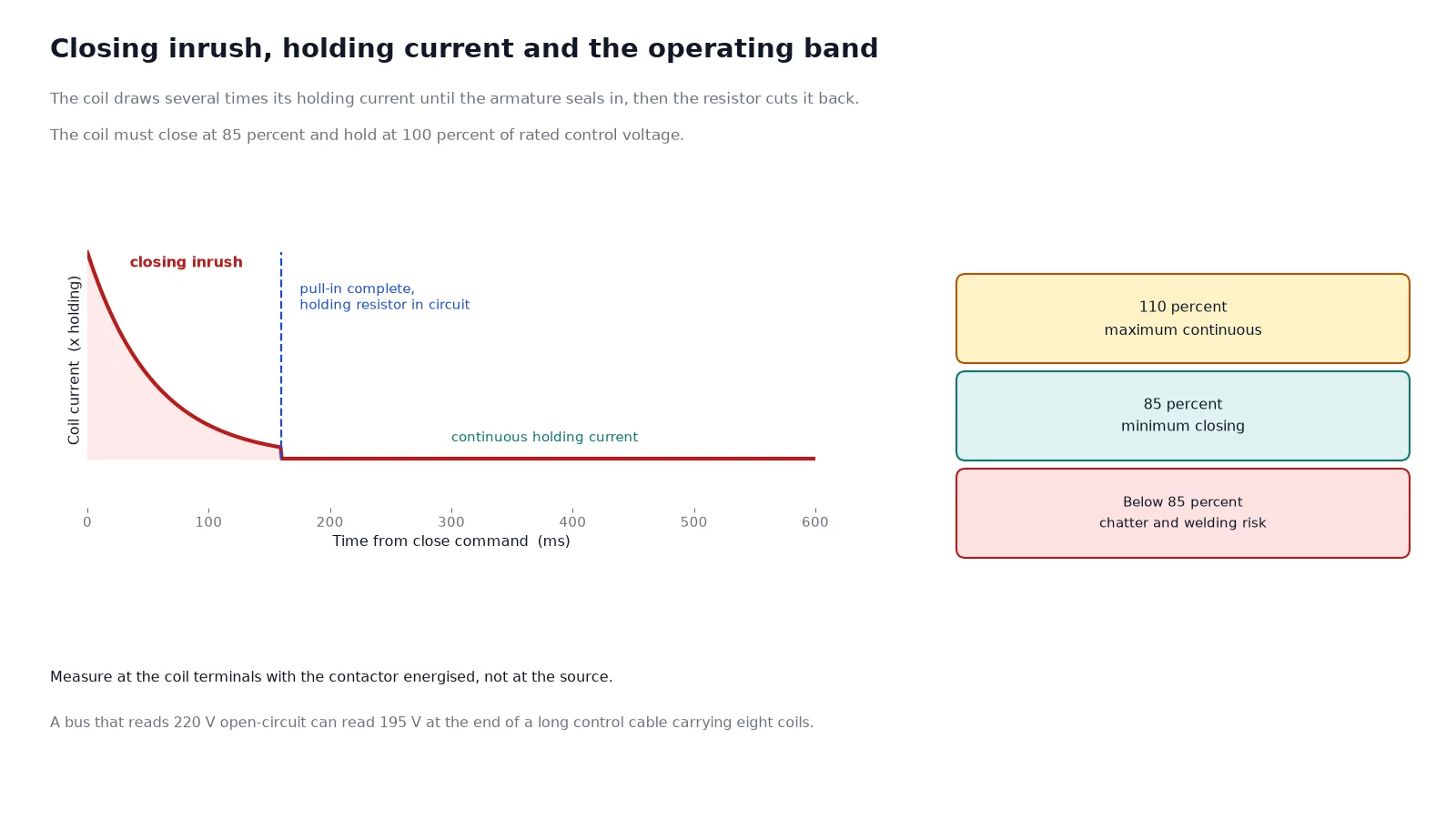
Switchgear standards require the operating device to close reliably between 85 percent and 110 percent of rated control voltage, and the coil must hold at 100 percent continuously. Below 85 percent the contactor may fail to seal in, and a contactor that almost closes is worse than one that does not close at all, because the main contacts touch with insufficient pressure and can weld.
| Condition | Typical behaviour | What to do |
|---|---|---|
| Control voltage under 85 percent at the coil | Chatter, late closing, contact welding risk | Increase control cable size, shorten the run, or move to a DC coil |
| Control voltage 85 to 110 percent | Designed operating band | Nothing; verify at the coil terminals, not at the panel bus |
| Control voltage above 110 percent continuously | Coil overheating, shortened insulation life | Check tap setting on the control transformer |
| Several coils closing simultaneously | Common bus dip, random drop-out | Stagger closing, or hold on DC with a local capacitor |
Measure at the coil terminals with the contactor energised, not at the source. A 220 V bus that reads 220 V open-circuit can read 195 V at a coil at the end of a 150 m control cable carrying eight coils.
On a typical medium-voltage vacuum contactor the control terminals sit on a separate low-voltage block, physically isolated from the main terminals, and the auxiliary contacts share that block. A CKG3 frame in the 160 A to 630 A range publishes three normally open plus two normally closed auxiliary contacts, and larger low-voltage frames such as the GKJ5 publish three normally open plus three normally closed. Plan your scheme against the published count, then confirm it on the drawing, because auxiliary arrangements are a build-to-order item on these frames. If you are still choosing between frame families, the CKG3, CKJ5 and JCZ5 comparison sets out where each one fits.
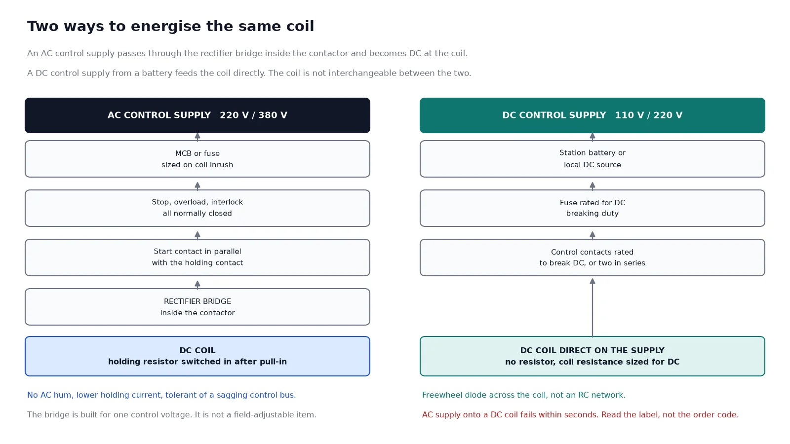
A workable wiring sequence for a single starter looks like this:
Note the order. Anything that must stop the contactor, including the emergency stop, the thermal overload and the upstream breaker’s normally closed contact, belongs in the coil circuit ahead of the start contact. Putting an interlock in the indication circuit instead of the coil circuit is a common panel-building shortcut and it defeats the interlock.
A contactor coil is not a resistive load. At the instant of closing, the armature is open and the magnetic circuit has a large air gap, so the coil draws several times its holding current, typically for 100 to 200 ms. On medium-voltage frames that inrush is measured in hundreds of volt-amperes, and it is what decides the control fuse and the control transformer.
| Item to size | Basis | Common mistake |
|---|---|---|
| Control fuse or MCB | Coil inrush plus all simultaneous loads | Sized on holding current, nuisance trip on every close |
| Control transformer | Sum of holding VA plus the largest single inrush | Sum of all inrush figures, which is impossible and grossly oversized |
| Control cable | Voltage drop under inrush, not steady state | Checked at holding current, coil chatters on long runs |
| Suppressor | RC across AC coils, freewheel diode across DC coils | Diode fitted to an AC coil, which shorts half the waveform |
The suppressor is not optional on a contactor that is switched by a PLC output or a small interposing relay. Breaking a coil circuit produces an inductive kick several times the control voltage, and that spike is what destroys the driving contact over a few thousand operations. Fit an RC network across an AC coil and a reverse-biased diode across a DC coil, at the coil terminals rather than at the panel terminals.
A mechanically latched vacuum contactor has two coils: a closing coil that pulls the armature in, and a trip coil that releases the latch. Both are short-time rated and neither may be left energised. That changes the control circuit in three ways. The closing coil needs its own holding contact that opens as soon as the latch engages, the trip coil needs a separate supply or at least a separate fuse, and the auxiliary contact that proves the latched state must be wired to the indication circuit so a failed latch is visible rather than silent.
On DC trip coils, the driving contact must be able to break DC. A small AC-rated auxiliary relay will arc and stick when it opens a DC 220 V trip circuit, so either use a DC-rated contact or series-connect two contacts of the same relay. This is the one place in the control circuit where the contact rating matters more than the coil rating.
Five items settle a vacuum contactor order without a second round of questions: main-circuit voltage and current, coil voltage and whether it is AC or DC, auxiliary contact count and arrangement, whether a mechanical latch is needed, and the installation altitude if the site is above 1,000 m. Frames in this class are offered in an ordinary version up to 1,000 m and a plateau version up to 4,000 m, and the second one is not a stock item, so it belongs in the first message rather than in the follow-up.
Send those five items with your single-line diagram and the control scheme, and the coil, the bridge and the auxiliary block will be built to match. If the main-circuit voltage is still open, the guide to contactor voltage classes from 1 kV to 12 kV narrows it down first, and the introduction to how a vacuum contactor works explains the mechanism behind the coil. If the control supply is still undecided, ask for the DC option: it costs little more and removes the chatter, the hum and the drop-out problem in one step.
Still unsure which coil your panel can supply? Send the control transformer rating, the coil count on the bus and the length of the control cable, and the coil voltage and the bridge can be fixed before the order. Send the scheme to our engineers and it comes back matched.
No. The rated voltage describes the main circuit insulation, for example 7.2 kV or 12 kV. The coil voltage is a low-voltage control value, typically 110 V or 220 V AC or DC, and it is specified separately on every order.
No. The coil will not develop enough holding force at half its rated voltage and will chatter or drop out under load, and the supply will be loaded by an inrush it was not sized for. Change the coil, not the supply.
An AC-energised magnet hums at twice line frequency by design, and a shaded pole or a DC conversion removes it. If a contactor that used to be silent starts humming, check for a dropped phase, a worn shading ring or a rectifier diode failure, in that order.
Holding current is a small fraction of the closing inrush, which is why the control fuse is sized on inrush and the control transformer on holding plus the largest single inrush. Read both figures from the coil data sheet rather than from the contactor nameplate.
Only if you specify a DC coil. Frames with an internal rectifier bridge accept an AC control supply and generate DC for the coil themselves, so the plant keeps its AC control bus and still gets the steady holding force.
Short-term overvoltage is tolerable and the contactor will operate, but continuous overvoltage overheats the coil and ages the winding insulation. If the control bus runs high, re-tap the control transformer instead of accepting it.
Wiring the coil correctly takes ten minutes and one photograph of the nameplate. Getting it wrong costs a coil, a commissioning day and sometimes a set of welded main contacts. If you are specifying several starters at once, send the control scheme with the enquiry and let the coil, the rectifier and the auxiliary block be built as one matched set.