A transformer turns ratio looks like the simplest number on the nameplate. Ten thousand volts over four hundred, twenty-five to one. It is also the number that most often goes wrong on site, and almost never because the transformer is faulty — because two different quantities share the same name. The nameplate gives you a ratio of line voltages. The winding gives you a ratio of turns, and on a Dyn11 unit those two numbers differ by a factor of 1.732.
That gap explains most of the confusion around ratio tests, vector groups and tap calculation. A technician who sets a turns ratio tester to a star-star connection on a delta-wye transformer sees a reading 73% away from the nameplate and concludes the unit is defective. A protection engineer who forgets the 30° displacement tries to parallel two units that can never be paralleled. This guide works through the three calculations in order — turns, vector group, tap — and shows where each one touches the other two.
Turns ratio is a phase ratio, the nameplate is a line ratio
Both windings sit on the same core, so they link the same flux, and the flux changes at the same rate. That is the whole of the transformer principle: the induced voltage per turn is identical in both windings. From Faraday’s law the RMS voltage per turn is
E / N = 4.44 × f × Bm × Ac
where f is frequency in hertz, Bm is peak flux density in tesla, and Ac is the net core cross-section in square metres. Because that quantity is the same on both sides, the ratio of the winding voltages equals the ratio of the turns — always, for every connection, at every tap. What changes with the connection is how the winding voltage relates to the terminal voltage.
| Connection |
HV winding voltage |
LV winding voltage |
Turns ratio vs line ratio |
| Yy0 |
VL / √3 |
VL / √3 |
Equal |
| Dd0 |
VL |
VL |
Equal |
| Yd11 |
VL / √3 |
VL |
Turns ratio = line ratio / √3 |
| Dyn11 |
VL |
VL / √3 |
Turns ratio = line ratio × √3 |
| Yzn11 |
VL / √3 |
VL / √3 per limb, 2 limbs in series |
Turns ratio = line ratio × √3 / 2 |
Take the most common distribution unit in the world: 10 kV to 0.4 kV, Dyn11. The nameplate ratio is 10,000 / 400 = 25.0. The delta high-voltage winding carries the full 10,000 V across each phase, so the HV phase voltage is 10,000 V. The star low-voltage winding carries 400 / √3 = 231 V per phase. The actual turns ratio is therefore 10,000 / 231 = 43.3, which is 25.0 × √3.
Neither number is wrong. They answer different questions. 25.0 is what an instrument transformer or a ratio tester connected across the terminals should measure. 43.3 is what the winding designer used to count turns. If you are checking a ratio test against a specification, make sure both sides of the comparison are the same kind of ratio — this single distinction accounts for more false alarms than every genuine winding fault combined.
Volts per turn fixes both windings at once
Working the formula above forwards gives the number that actually sizes a transformer. At 50 Hz, with a grain-oriented silicon steel core run at 1.65 T peak and a net core area of 0.02 m², the induced voltage per turn is 4.44 × 50 × 1.65 × 0.02 = 7.33 V per turn.
Apply that to the 10 kV / 0.4 kV Dyn11 unit: the HV winding needs 10,000 / 7.33 = 1,365 turns, and the LV winding needs 231 / 7.33 = 31.5 turns. The half turn on the low-voltage side is real — it is why low-voltage windings are often wound as two parallel paths or with a fractional turn compensated by the delta connection of an interleaved section.
Two consequences follow directly, and both matter in the field.
The first is that flux density is set by the supply voltage, not by the load. A transformer rated for 1.65 T at 10 kV, fed at 11 kV, runs at 1.82 T: no-load current climbs steeply, the core audibly complains, and no-load loss and noise both rise. Over-voltage is a core problem; over-load is a copper problem. They are cured differently.
The second is that a single shorted turn barely moves the ratio. One shorted turn out of 1,365 is 0.073% — inside the ±0.5% tolerance of the ratio test, so the test passes. What a shorted turn does move is local temperature and dissolved gas. A ratio test proves the turn count is broadly right; it does not prove the winding is healthy. That is why ratio, winding resistance, insulation resistance and DGA are read together and never one at a time.
Vector groups: a clock face in 30° steps
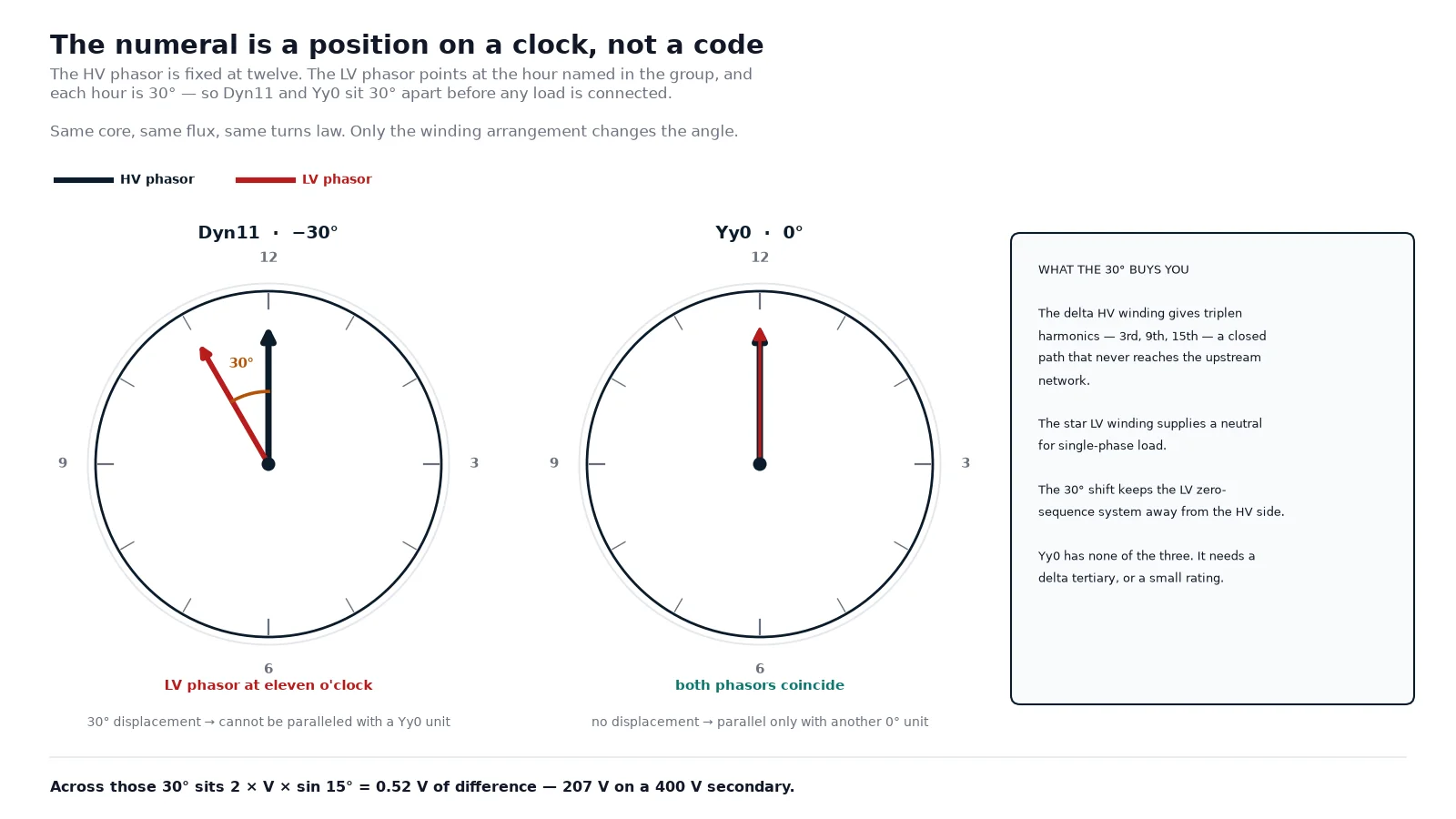
The vector group records the angular displacement between the high-voltage and low-voltage phasors, written on a clock face. The HV phasor is fixed at twelve; the LV phasor sits at the hour given by the numeral, and each hour is 30°. The letters before the numeral give the connections — upper case for HV, lower case for LV, n for a brought-out neutral, z for zig-zag.
Dyn11 therefore means: delta HV, star LV with neutral brought out, LV phasor at eleven o’clock — a displacement of 330°, which is the same angular distance as −30°. The magnitude of the shift is what the numeral encodes; the sign convention is what the protection relay and the phasing check care about, and it is safer to confirm the direction on site with a phasing set than to derive it from the drawing.
Why does Dyn11 dominate distribution networks? Three reasons, and only the first is usually quoted.
The delta HV winding gives circulating triplen harmonics — third, ninth, fifteenth — a closed path inside the delta, so they never reach the upstream network. The star LV winding provides a neutral for single-phase load, which is the whole point of a distribution transformer. And the 30° shift means the zero-sequence system on the LV side is isolated from the HV side, so an unbalanced LV load does not put zero-sequence current into the HV network.
Compare that with Yy0, which has no delta path and therefore no way to absorb triplen flux: the third-harmonic flux has to return through the tank and structural steel, heating it and producing a distorted secondary voltage. Yy0 units either carry a delta-connected tertiary stabilising winding or are limited to small ratings where the effect is tolerable. Dd0 has no neutral at all and is used where the load is balanced three-phase. Yzn11 is the earthing-transformer connection — the zig-zag gives a low zero-sequence impedance, so a small unit can supply a large earth-fault current.
| Vector group |
Displacement |
What it is good at |
Where you meet it |
| Yy0 |
0° |
Simple, cheap, high voltage per turn |
Small unit substations, with a delta tertiary on larger ratings |
| Dyn11 |
−30° |
Triplen harmonic rejection, LV neutral, zero-sequence isolation |
Distribution transformers, 11 kV to 35 kV class |
| Dd0 |
0° |
Balanced three-phase load, no neutral required |
Rectifier and drive transformers, industrial feeders |
| YNd11 |
−30° |
Solidly earthed HV neutral, delta LV for stability |
Generator step-up, transmission interties |
| Yzn11 |
−30° |
Low zero-sequence impedance |
Earthing transformers, auxiliary earthing of unearthed systems |
What a 30° shift does when you try to parallel
Two transformers can only be paralleled if, at every instant, the secondary voltages of corresponding phases are in phase. Thirty degrees of displacement breaks that condition permanently, and the size of the consequence is easy to calculate.
If two 400 V secondaries are 30° apart, the voltage between corresponding terminals is 2 × 400 × sin(15°) = 207 V. That difference drives a current limited only by the two short-circuit impedances. For a 1,000 kVA 400 V unit at 4% impedance, the impedance is 6.4 mΩ; two in series gives 12.8 mΩ, so the circulating current is 207 / 0.0128 ≈ 16 kA against a rated current of 1,443 A. Nothing about that is marginal: the protection operates, or the windings are damaged before it does.
A Dyn11 against a Dyn1 pair is worse — 180° apart, so the difference voltage is 2 × 400 = 800 V. A Yy0 against a Dyn11 pair is the classic mistake in a plant expansion, because both units look identical on the outside and the nameplate is the only warning.
The conditions for paralleling are worth writing into the switching procedure rather than leaving to memory. Same vector group, or at least a zero net displacement between the two units. Ratio within ±0.5%, which in practice means matching tap positions. Short-circuit impedance within about ±10%, so the load divides roughly in proportion to rating rather than being dictated by impedance. A rating ratio no worse than 3:1, because beyond that the smaller unit contributes little and carries a disproportionate share of the reactive circulating current. And the same phase rotation, proved with a phase sequence meter rather than assumed from the cable colours.
Impedance mismatch and vector group mismatch fail in the same way — circulating current — but they are graded differently. Impedance mismatch produces a modest circulating current that costs you a little capacity. Vector group mismatch produces a fault. The impedance calculation itself is covered in the guide to short-circuit impedance and voltage drop.
Tap calculation: what a ±2.5% step really changes
Most distribution transformers carry an off-circuit tap changer on the high-voltage winding, typically ±2 × 2.5% in five positions. Tapping the HV side is a manufacturing decision: the HV winding carries the smaller current, so the tap leads are thinner, the tap switch is cheaper, and the LV output stays inside a narrow band instead of moving by the full tap range. On the oil-immersed distribution transformers built for 11 kV to 35 kV networks, this is the standard arrangement.
The calculation is a ratio, not a subtraction. Adding 5% turns to the HV winding does not reduce the secondary voltage by 5% — it reduces it by 1/1.05, which is 4.76%. The distinction is small at 2.5% but it is the difference between a calculation that reconciles with a measurement and one that does not.
| Tap position |
HV turns |
Secondary volts (400 V base) |
Core flux |
| +5% |
105% |
381 V |
95.2% |
| +2.5% |
102.5% |
390 V |
97.6% |
| Nominal |
100% |
400 V |
100% |
| −2.5% |
97.5% |
410 V |
102.6% |
| −5% |
95% |
421 V |
105.3% |
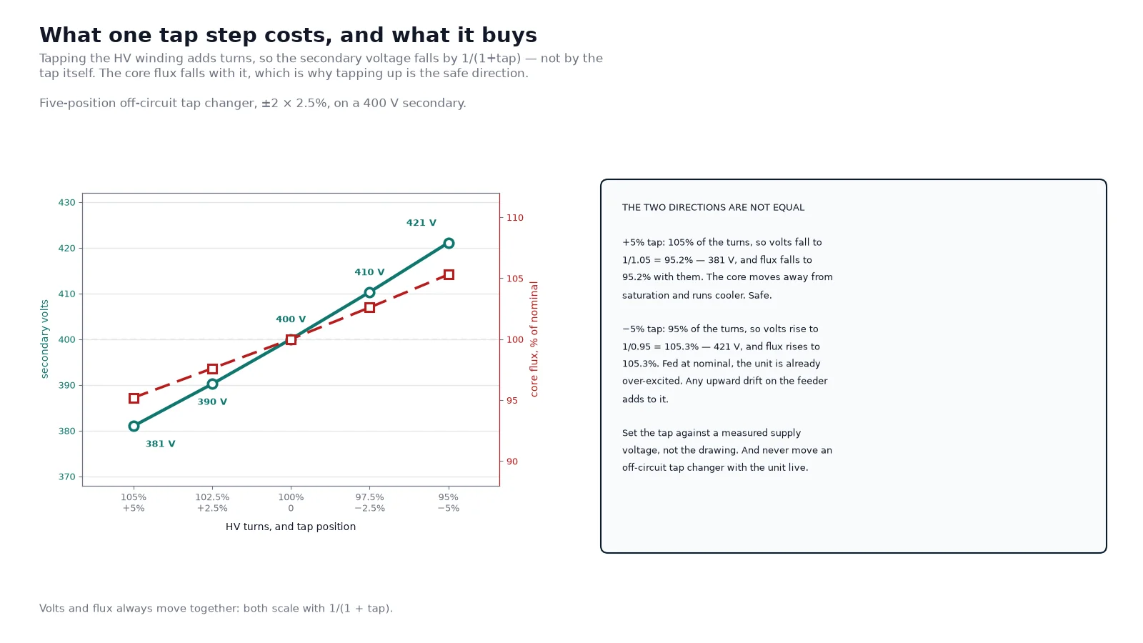
The flux column is the part that gets ignored, and it is the part that matters for reliability. Tapping towards a higher HV turn count lowers the volts per turn, so the core runs cooler and further from saturation — the safer direction. Tapping the other way raises the flux, so a unit on the −5% tap fed at nominal voltage is already at 105% flux, and any upward drift in the supply pushes it toward saturation and a steep rise in no-load loss and audible noise.
Two rules follow. Set the tap against a measured supply voltage, not against the nominal figure on the drawing, because a feeder sitting 4% high will erase the margin you thought you had. And never operate an off-circuit tap changer with the transformer energised — it has no breaking capacity, and the arc will destroy the contacts. On-load tap changers exist for that duty and are built to a different standard entirely; the difference between the two is set out in OLTC versus off-circuit tap changer.
Tapping also moves the short-circuit impedance a little, because the winding geometry changes with the tap section in circuit. The effect is small on a ±5% range and is normally absorbed by the impedance tolerance, but a wide tapping range on a large unit should be checked at both extremes rather than only at the principal tap.
Reading a ratio test without fooling yourself
A turns ratio tester energises one winding at low voltage and measures the other, then compares the result with the declared ratio. Four things decide whether the number means anything.
Tell the instrument the vector group. Set a Dyn11 unit as Yy on the tester and every reading will be out by √3 — 43.3 reported against a declared 25.0. Nothing is wrong with the transformer.
Compare like with like. The declared ratio at the principal tap is a line-to-line figure. Test results and acceptance limits must be on the same basis. The common tolerance is ±0.5% of the declared ratio at the principal tap, applied in the same way the rest of the nameplate is read.
Sweep every tap. The ratio should march in equal, monotonic steps from one end of the range to the other. A tap that repeats the previous value, or jumps, points to a wrong tap lead or a contact that is not closing — a mechanical fault that a single-point measurement at the principal tap will never show.
Compare the three phases. Phase-to-phase spread of more than a few tenths of a percent on a three-phase unit is a winding or connection problem, even when each individual phase is inside the ±0.5% band.
Where each number lands in a specification
These four quantities belong on the inquiry, not in a follow-up email. A supplier who has all of them can quote without assumptions, and a specification that omits them will be filled in with whatever is on the shelf.
| Item |
What to state |
Why it decides the quote |
| Rated ratio |
HV and LV line voltages, and the vector group |
Fixes the turns count, the core size and the winding arrangement |
| Tapping |
Range, step, number of positions, off-circuit or on-load |
Changes the winding length, the tap switch and the price |
| Vector group |
The exact designation, not just “Dyn” |
Determines paralleling compatibility and harmonic behaviour |
| Impedance |
Percentage at the principal tap, with a tolerance |
Sets fault level, voltage regulation and paralleling behaviour |
For a dry-type unit the same four are read against the temperature-rise class as well, since the class fixes how much flux and current the insulation will tolerate over life; the dry-type transformer specification guide covers that side, and the cast-resin range shows how the group and tap options are offered as standard. If the project feeds a mix of delta and star loads, or parallels a new unit with an existing one, the vector group is the first item to settle — everything else can be adjusted later at a price, but the connection cannot.
Frequently asked questions
What is the turns ratio of a 10 kV to 0.4 kV transformer?
On a Dyn11 unit the nameplate ratio is 25.0 and the winding turns ratio is 43.3. The difference is the √3 between the delta HV phase voltage, which equals the line voltage, and the star LV phase voltage, which is the line voltage divided by √3. On a Yy0 unit of the same voltages both figures would be 25.0.
Is turns ratio the same as voltage ratio?
Only when both windings use the same connection type. Yy and Dd units have equal line and turns ratios. Mixed connections — Yd, Dy, Yz — introduce a √3 between them, in one direction or the other. This is the single most common source of a “failed” ratio test on a healthy transformer.
What does Dyn11 actually mean?
Delta high-voltage winding, star low-voltage winding with the neutral brought out, and the LV phasor at eleven o’clock against the HV phasor at twelve — a 30° displacement. The numeral is not a quality grade or a version number; it is a position on a clock face, and each hour is exactly 30°.
Can a Dyn11 transformer be paralleled with a Yy0 unit?
No. The 30° displacement puts roughly 52% of rated voltage between corresponding secondary terminals, which drives a circulating current limited only by the two short-circuit impedances. At 400 V that is about 207 V of difference. Paralleling requires matching vector groups, matching tap positions, impedance within about ±10%, and the same phase rotation.
Does moving the tap change the turns ratio?
Yes — that is precisely what it does. A +5% tap adds 5% more HV turns, which raises the turns ratio and lowers the secondary voltage by 4.76%, not 5%. It also lowers the core flux by the same 4.76%, which is why tapping up is the safe direction and tapping down eats over-voltage margin.
How do you calculate turns per volt?
Divide the induced voltage per turn from 4.44 × f × Bm × Ac. At 50 Hz, 1.65 T and 0.02 m² that gives 7.33 V per turn, so a 10 kV winding needs about 1,365 turns. Both windings must be designed to the same volts per turn, because they share one core and one flux.
What to carry into the inquiry
Three numbers decide whether a transformer order goes smoothly: the ratio stated as a line-to-line figure with its vector group, the tap range with its step and type, and the impedance with a tolerance. Add the temperature-rise class for a dry-type unit and the specification is complete enough to quote without assumptions.
If the unit has to parallel with something already installed, send the existing nameplate as well. Vector group and impedance mismatches cannot be fixed after the windings are wound, and a 30° error is not a commissioning problem — it is a purchase-order problem that surfaces as a trip on the first close. Our transformer manufacturing and testing pages set out how ratio, impedance and vector group are proved at the factory, and the engineering team can check a proposed vector group against your single-line diagram before the order is placed.
For units that will run close to their thermal limit, the other half of the picture is on the monitoring side: winding hot-spot monitoring and temperature controller setup covers where the sensor has to sit and what the fan, alarm and trip points should be.