A transformer oil leak is never just a stain on the concrete. Oil is doing four jobs at once inside an oil-immersed power transformer — dielectric, coolant, arc suppressant and moisture barrier — and every litre that leaves the tank is a litre no longer doing any of them. The tank does not run dry, which is exactly why the leak gets ignored until the oil level alarm does the arguing for you.
What follows is the field view: where these leaks actually occur, which causes are worth fixing and which are worth replacing, how to grade a leak so you send the right crew, and what to put in a purchase specification so the next unit does not repeat the pattern in year three.
What a leak costs before it becomes a failure
Oil leaks account for something like 15–25 % of all transformer maintenance incidents in the surveys that bother to count them, and the mechanism is always the same three-step slide:
- The level drops. The top of the winding is exposed, the cooling circuit loses its driving head, and the parts that were designed to be oil-cooled start running hotter than the thermal model assumes.
- The tank breathes in. A leak works in both directions. Every thermal cycle that pushes oil out pulls moist air and dust in through the same path, and the silica gel in the breather cannot dry air that enters through a gasket.
- The paper absorbs it. Cellulose is hygroscopic and will take water out of the oil until the two reach equilibrium. At that point the failure mode is no longer a leak — it is insulation ageing, and the leak was the early warning nobody acted on.
There is a fourth step that is worse and more expensive: a leak that is allowed to reach a hot surface, a cable joint or a bund that no longer holds. That is a fire risk and a regulatory event, not a maintenance item.
Where oil actually escapes
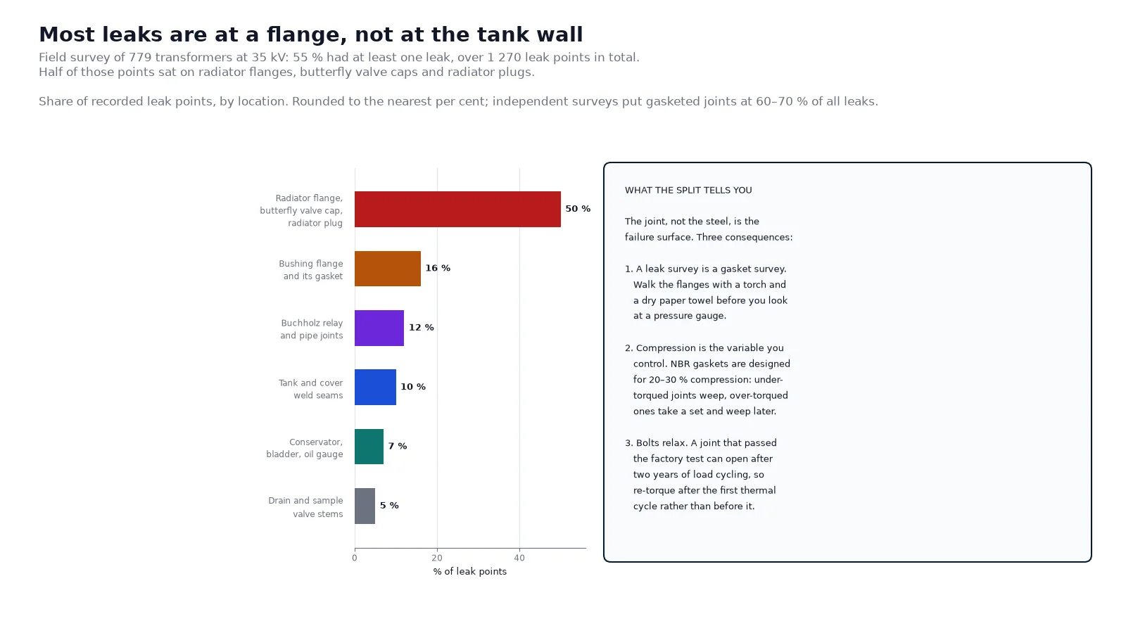
The distribution above comes from a field survey of 779 transformers at 35 kV, of which 55 % had at least one leak and which together produced more than 1 270 leak points. Half of those points sat on radiator flanges, flat butterfly valve caps and radiator plugs. Bushing flanges accounted for 16 %, Buchholz relay interfaces for 12 %.
Independent surveys land in the same place, with gasketed joints responsible for something like 60–70 % of all leaks. The lesson is uncomfortable for anyone who assumes a leak means a bad weld: the joint, not the steel, is the failure surface. A leak survey is a gasket survey.
Cause 1: gaskets that took a set
Rubber seals by stored elastic stress. The gasket is compressed when the joint is torqued, and it keeps sealing only for as long as it is still pushing back against the flange. Three things destroy that:
- Compression set. Compress a gasket beyond its design range and the material stops recovering. Nitrile gaskets are designed around 20–30 % compression; the manufacturer’s torque figure exists to hold the joint in that window, not to make it as tight as possible.
- Heat. Nitrile (NBR) is comfortable from about −40 to +100 °C. A pad-mounted unit running well above nameplate in a hot climate pushes bushing adapters past that, which is where fluoroelastomer (FKM, −20 to +200 °C) earns its price. Note the two materials that look attractive and are not: EPDM swells in hydrocarbon oil and should never be used on an oil joint, and silicone is poor in mineral oil despite its temperature range.
- Thermal cycling. Every load cycle expands and contracts the oil and the tank. The gasket is the part that absorbs that movement, and it is the part that eventually stops.
The failure signature is a weep, not a flood: a dark film along the bottom edge of a flange, dust stuck to it, a drip that forms over hours. A joint in this condition can often be re-torqued once, in a cross pattern, to the maker’s figure. It cannot be re-torqued twice.
Cause 2: weld seams, porosity and corrosion
A weld defect that leaves the factory — a pinhole, an incompletely fused root, a sand inclusion under the paint — is a leak waiting for a pressure cycle. Tank pressure changes with load and with ambient temperature, and a pore that held at the factory test opens at the thousandth cycle. Lower-tank welds carry more oil head and are statistically more likely to be the ones that go.
Corrosion is the slower version. A tank wall that thins from the outside in, usually at a support, a lifting lug or a point where water sits, eventually reaches a pinhole. Coastal and industrial atmospheres move this forward by years.
Weld leaks are the ones where the repair method matters most, because welding on a tank full of oil is a fire job with a very short list of acceptable mistakes. The oil level is dropped below the leak, the area is cleaned to bare metal, and the arc time is kept short and intermittent — 10–20 seconds at a time — so the heat does not cook the gasket on the nearest flange. A fire watch and extinguishers are part of the procedure, not a precaution.
Cause 3: bushings and the thermal mismatch
A bushing is a porcelain or composite body clamped into a steel tank through a gasket, carrying a conductor that heats and expands. That is three materials with three expansion coefficients in one joint, and it is asked to hold a seal for twenty years.
The usual paths are a gasket that has lost compression, a clamping nut that has loosened, or a sealing surface that was scratched during installation. The failure mode is more dangerous than a flange weep because oil tracking down the bushing body can bridge the creepage path and turn a leak into a flashover. Any oil on a bushing, at any rate, is a de-energise-and-look job.
Cause 4: valves, gauges and pressure relief
Drain valves, filter-press valves, sample valves and pressure relief devices are their own family of leaks, and they are frequently left out of the survey because they are small and awkward to reach. Valve stem packings wear; a sample valve that was not fully closed after the last oil sample weeps until someone notices. A pressure relief device with a degraded diaphragm is worse: it does not leak until it lifts, and then it may not reseat.
The cheap fix is procedural — cap the sample valve, log every sampling operation, and include the valve stems in the walk-round. The expensive fix is discovering a relief device that has been weeping into a bund for a year.
Cause 5: the conservator, the bladder and the breather
The conservator system is where a small leak causes a large problem. A rubber bladder in a sealed conservator typically lasts three to five years in a hot climate before it cracks; when it does, oil can migrate to the air side and the oil level gauge starts reporting a level that has nothing to do with the oil in the tank.
A blocked breather is the mirror image. The tank can no longer equalise pressure as the oil expands, so internal pressure rises and the oil finds the weakest joint on the unit — usually a flange that was perfectly tight. If a unit starts leaking at several joints at once, check the breather before ordering gaskets.
This is also the reason the choice between a sealed tank and a conservator matters at specification stage; the two designs fail differently, and sealed versus conservator construction sets out what each one asks of maintenance.
Cause 6: handling damage and installation errors
A tank that was lifted by its radiators, dropped off a pallet, or dragged across a yard will leak at the point where the stress concentrated. Installation errors are quieter: a gasket installed off-centre, a flange face with paint or weld spatter on it, bolts tightened in a circle rather than in a cross pattern so the flange tilts and one side loses compression.
Most of these are invisible until the first thermal cycle. Installation requirements covers the checks that catch them while the crane is still on site, which is the only time they are cheap to fix.
Grade the leak before you send a crew
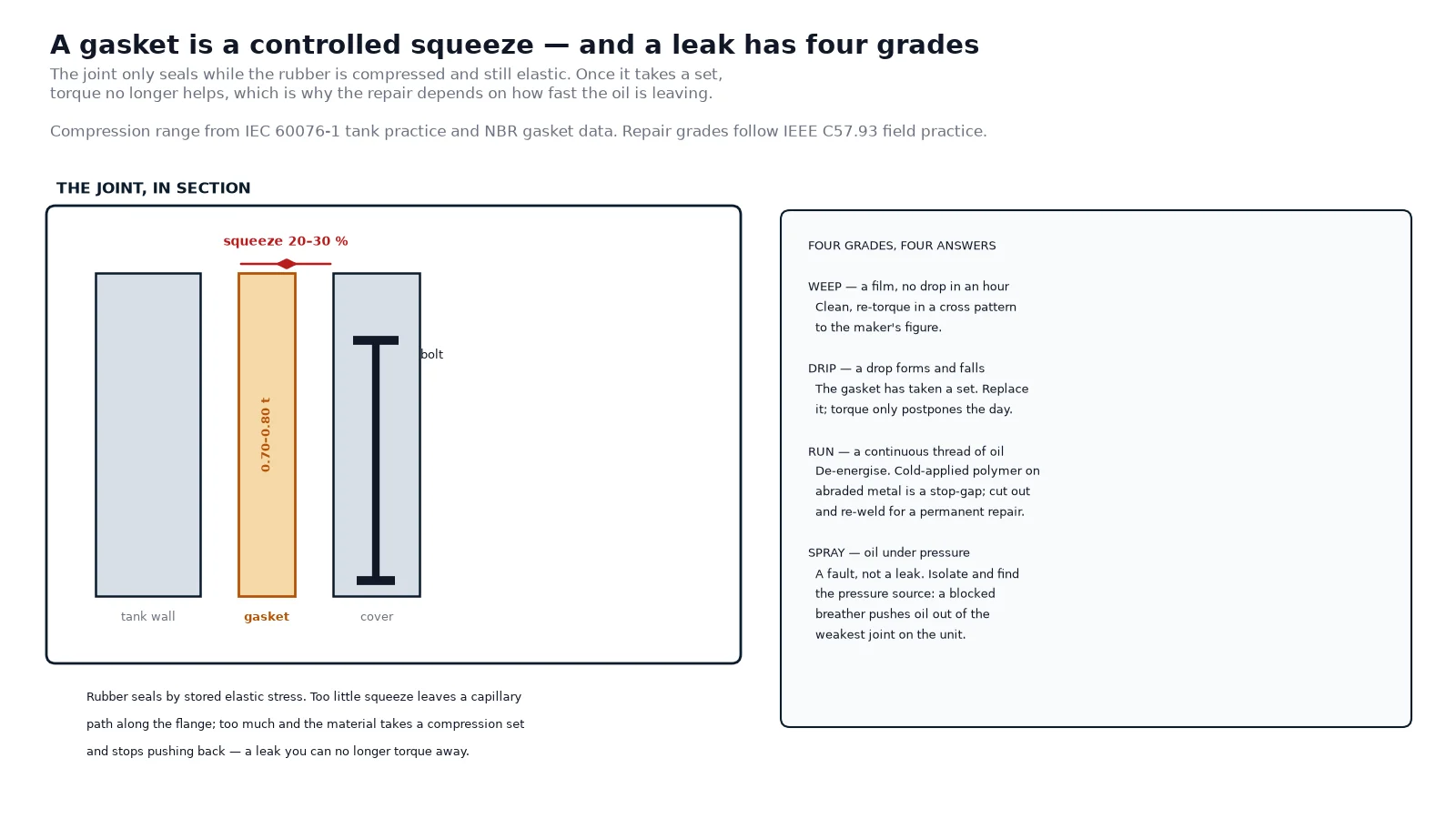
Four grades, four different answers. The grade is set by rate, not by how bad it looks:
| Grade |
What you see |
What it needs |
| Weep |
A film, no drop forming within an hour |
Clean, re-torque in a cross pattern to the maker’s figure, monitor monthly |
| Drip |
A drop forms and falls |
Gasket has taken a set — replace it; torque only postpones the day |
| Run |
A continuous thread of oil |
De-energise. Cold-applied polymer as a stop-gap, cut out and re-weld for a permanent repair |
| Spray |
Oil leaving under pressure |
Treat as a fault: isolate and find the pressure source — blocked breather, failed bladder, over-filled tank |
The spray grade deserves its own line because it is the one that gets misdiagnosed. Oil leaving a joint under pressure means the tank is being pressurised from somewhere, and re-gasketing it will simply move the leak to the next weakest point.
If you only need to decide who to send, the cause map is shorter:
| What you find |
Most likely cause |
First action |
| Film along a flange underside, dust stuck to it |
Gasket has lost compression |
Re-torque in a cross pattern, monitor for a month |
| Oil on the bushing body or the turret |
Bushing gasket or loose clamping nut |
De-energise and inspect — tracking risk, not just oil loss |
| Stain at a weld, spreading downward |
Porosity or an incompletely fused root |
Clean to bare metal, confirm with a pressure test before welding |
| Leak appears at several joints at once |
Blocked breather or failed bladder pressurising the tank |
Check the breather and the gauge reading before touching any gasket |
| Oil level gauge reads high but the tank is low |
Bladder perforated, oil on the air side |
Isolate the conservator and replace the bladder |
| Damp patch under a radiator, not at a flange |
Corrosion thinning or a seam crack |
Ultrasonic thickness check, then weld repair or radiator replacement |
Repairs that hold
Re-torque
Only for a weep, and only once. Cross pattern, calibrated torque wrench, the manufacturer’s figure — not “as tight as it goes”. Over-torquing is one of the most common causes of a joint that leaks again within a year, because it takes the gasket past its compression set point on day one.
Re-gasket
The reliable repair for a drip. Drop the oil below the joint, dismantle, clean both faces, check flatness and finish, fit an oil-compatible gasket of the right hardness, and torque in a cross pattern in two or three passes. A flange face that is not flat will defeat a new gasket just as it defeated the old one, so check it while the joint is open.
Cold-applied polymer plug
For a running leak on a weld or a small pore, and for cases where an outage is genuinely not available. The surface is cleaned, abraded to give the polymer something to key into, wiped with a solvent, and the mixed compound is applied and left to cure. Field cases report running weld leaks stopped within hours without an outage. Treat it as a stop-gap that buys time, and record it — the next person to open that tank needs to know it is there.
Weld repair
The permanent answer for a weld defect. Drain below the leak, clean to bare metal, weld in short intermittent passes, inspect, and then pressure-test the tank. A weld repair that is not pressure-tested has not been verified, only attempted.
The test that proves the repair
IEC 60076-1 clause 11.8 sets the factory leak test: apply pressure at least 30 kPa above the normal operating oil pressure, hold for 24 hours on units above 20 MVA or above 72.5 kV, and 8 hours on everything smaller, then inspect the whole unit for leakage. In practice most workshops test at 35 kPa or so and brush soap solution along every joint during the hold, because a pressure gauge alone will not find a weeping gasket — it only reports the leak once enough oil has left to move the needle.
For site work, clause 11.11 is the useful one: evacuate to the maximum vacuum the site work requires, hold for two hours, then isolate the pump and watch the pressure rise, which should stay below 0.2 kPa per hour over at least 30 minutes. That is a demanding figure — on a 5 m³ tank it corresponds to roughly a litre of air per hour — and it is the test that separates a genuinely sealed tank from one that merely is not dripping yet.
Whatever the method, the record should name the individual unit: pressure held, hold time, ambient temperature, and who signed it. A leak that leaves the factory becomes a warranty claim in another country, and by then the only thing that matters is whether the test was real.
What to specify so it does not leak in year three
- A gasket callout, not a material name. Ask for the ASTM D2000 line number with hardness and compression-set limits, so the joint is defined in writing rather than by whichever sheet was in the bin.
- A torque table and a tightening sequence, plus the re-torque interval after the unit is energised and load-cycled.
- A flange face finish. Around 3.2 µm Ra is a reasonable default; a gasket cannot bridge a warped flange.
- The leak test pressure, duration and acceptance criteria, stated as a value and confirmed in a signed record for each unit.
- Fasteners for the environment. Stainless or hot-dip galvanised hardware on coastal, desert and high-humidity sites, because a rusted bolt cannot hold torque.
- A spare gasket kit and the torque table shipped inside the tank compartment. The fastest repair on a pad is your own crew with the right parts.
None of that is expensive at order stage. All of it is expensive after the pad is poured, and the cost of access — a permit, an excavation, a weekend outage in a city vault — dwarfs the cost of the parts by an order of magnitude. That asymmetry is the whole argument for specifying the joint rather than accepting it.
A leak is also a moisture problem
Fix the leak and the job is half done. The tank has been breathing through that path for however long the leak existed, and the paper has been absorbing the water. After the repair, an oil test tells you where the insulation actually stands: water content, breakdown voltage, acidity, and dissolved gas if the unit has been running hot or wet for a while. DGA interpretation is the fastest way to find out whether the moisture arrived alone or brought a thermal fault with it.
The oil-immersed maintenance schedule sets the intervals for those tests and for the gasket walk-round, and it is worth aligning the two: the walk-round finds the leak, the oil test tells you what it cost. If the paper has already taken up the water, the four field drying methods cover how to get it back out and how to tell when the job is actually finished.
What to carry into the inquiry
Whether the outcome is a repair kit, a service visit or a replacement unit, the same six facts decide the answer: kVA and voltage class, tank construction (sealed or conservator), the leak locations and their grades, how long the leak has been present, the last oil test result with its water content, and the ambient conditions the unit sits in. With those, a supplier can tell you whether the problem is a joint, a design detail or a unit that has reached the end of its economic life — and a manufacturer who builds to a stated leak-test standard can quote a replacement that will not repeat it.
Frequently asked questions
Can a transformer keep running with an oil leak?
A weep, yes, with monitoring and a scheduled repair. A drip should be scheduled within weeks, not months. A run or a spray is a reason to de-energise: the first because oil loss can expose the winding, the second because it usually means the tank is being pressurised from a blocked breather or a failed bladder and the next joint to go may not be a flange.
Why does my transformer leak only when it is loaded?
Because load raises oil temperature, oil expands, and internal pressure rises. A joint that is marginal at 20 °C can hold and still weep at 70 °C. The same mechanism explains leaks that appear in summer and stop in winter — the seal is not changing, the pressure is.
Is it safe to weld a leaking transformer tank?
Only under a controlled procedure: de-energised, oil level dropped below the leak, area cleaned to bare metal, short intermittent arc times, a fire watch and extinguishers on site. Transformer oil has a flash point above 140 °C but the vapour space above it is the hazard, and welding near a tank that has not been properly prepared is how tank fires start.
What is the difference between a weep and a leak in a specification?
Specifications usually define it by rate — a weep is a film or a stain that does not form a falling drop within a stated period, while a leak forms drops. That definition matters commercially because acceptance criteria are written against it, so it is worth agreeing the period and the inspection conditions before the unit ships.
How often should transformer gaskets be replaced?
On condition, not on a calendar. A conservator bladder is the exception, where three to five years is a realistic service life in hot climates. For flange gaskets, replace when a joint weeps after a re-torque, when the gasket has visibly hardened, or whenever the joint is opened for another reason — a gasket that has been compressed once should not be reused.
Does a small oil leak really matter?
Two ways. The oil lost is a small cost; the moisture that enters through the same path is not. A weeping conservator gasket left for six months has been observed to take oil water content from around 8 ppm to over 40 ppm, with dissolved hydrogen appearing in the DGA at the same time. A gasket job became an oil reconditioning and monitoring programme.