Transformer Protection Coordination: Main and Backup
Coordination belongs to a set of relays, not one device. Damage curve, inrush blocking, CT saturation and a worked grading example at 1 000 kVA.
Read More

A transformer short circuit withstand rating is not a promise that the unit survives any fault. It is a claim about one specific event: a bolted short circuit at the terminals, with the current held at a defined level for a defined time, after which the winding must still pass its dielectric routine tests and still measure its original impedance. IEC 60076-5 is the standard that defines that event, and most of the argument in a specification review is about which of the two halves of it — thermal or dynamic — has actually been proven for the unit you are buying.
The distinction matters commercially. A supplier can hand you a short-circuit test report that is genuine, issued by an accredited laboratory, and still irrelevant to your order, because the report belongs to a different winding type, a different clamping arrangement or a different conductor. This article walks through what the standard calculates, what the test actually applies, how acceptance is judged, and the four sentences that should appear in your RFQ.
IEC 60076-5 splits transformers into three categories, and the category decides how much of the requirement is verified by calculation and how much by test:
The standard then defines two separate abilities. Thermal ability is the winding’s capacity to absorb the fault energy without the conductor temperature exceeding the limit for its insulation. Dynamic ability is the winding’s capacity to absorb the mechanical forces of the first cycles without permanent deformation. Thermal ability may be demonstrated by calculation. Dynamic ability cannot — it is a structural property, and the standard’s route to proving it is a type test on a representative design.
A short circuit is treated as adiabatic, because the heat generated in two seconds has no time to leave the conductor. IEC 60076-5 gives the final average winding temperature as:
θ₁ = θ₀ + 2(θ₀ + 235) × J² × t / 106 000 − 1 (copper)
where θ₀ is the initial winding temperature in °C, J the short-circuit current density in A/mm², and t the duration in seconds. For aluminium the constants change: 225 instead of 235, and 45 700 instead of 106 000. The initial temperature is taken as the maximum ambient plus the rated winding rise, which is why a Class F design starts its calculation 40 °C higher than a Class A one and therefore has less headroom, not more.
| Insulation class | Rated rise (°C) | Design θ₀ (°C) | θ₁ limit (°C) |
|---|---|---|---|
| A (105 °C), oil, copper | 60 | 100 | 250 |
| A (105 °C), oil, aluminium | 60 | 100 | 200 |
| F (155 °C), dry type | 100 | 140 | Per class, typically 180–250 |
| H (180 °C), dry type | 125 | 165 | Per class, up to 350 for Class 220 |
Note what actually drives the result: the fault current density, not the kVA. Take a 1 000 kVA, 10/0.4 kV unit at 6% impedance with a rated current density of 2.2 A/mm². The fault raises the density to 2.2 / 0.06 = 36.7 A/mm², and the calculation gives θ₁ ≈ 116 °C against a 250 °C limit. Reduce the impedance to 4% and the density rises to 55 A/mm², but θ₁ only reaches about 137 °C. Thermal withstand is therefore rarely the binding constraint on a distribution transformer. It becomes one on units designed with high current density — compact low-loss designs, or conductors sized for efficiency class rather than fault duty.
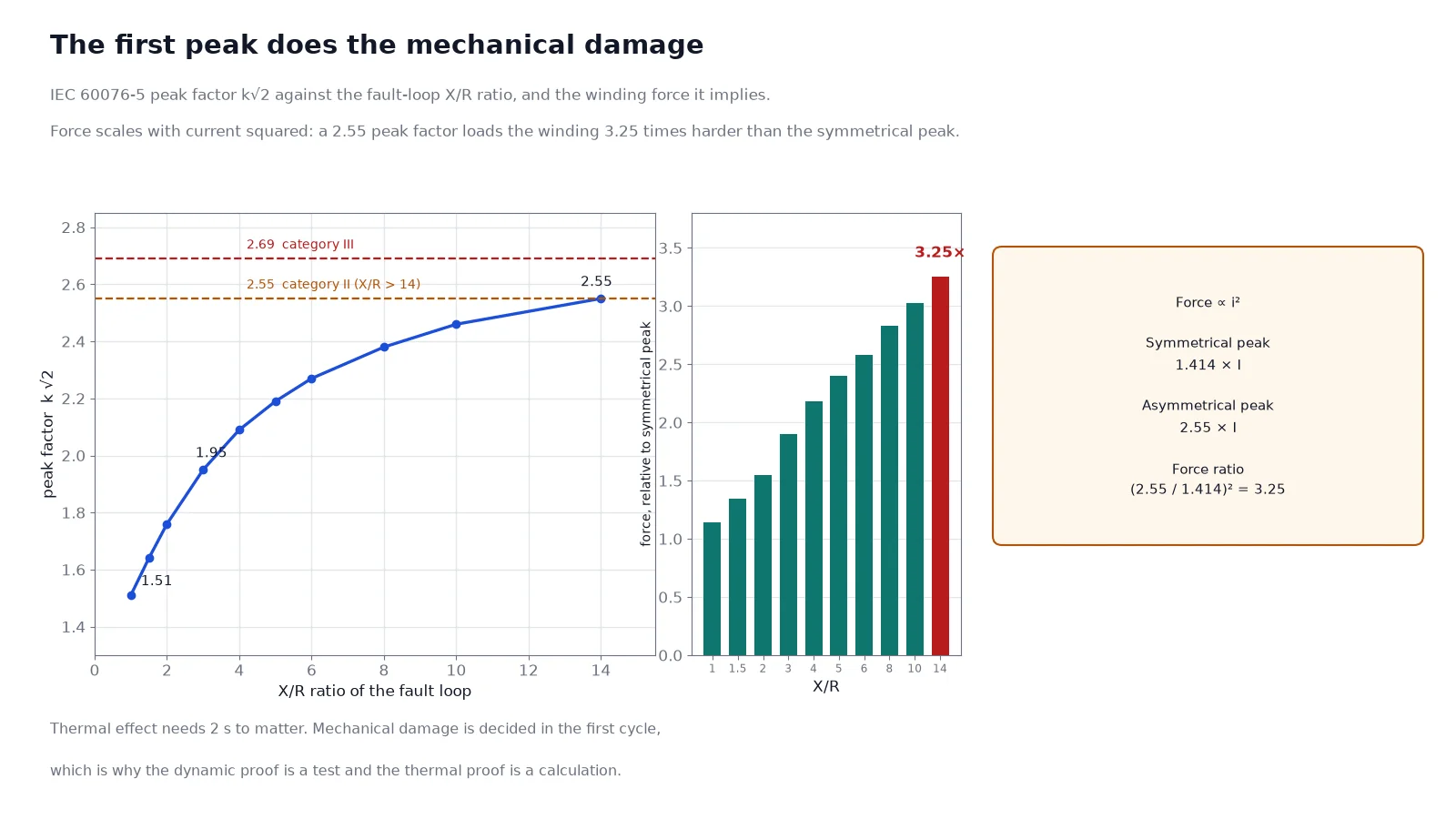
Mechanical force scales with the square of instantaneous current, so the number that damages a winding is the first asymmetrical peak, not the rms value. IEC 60076-5 defines it as î = I × k × √2, where k accounts for the DC offset and √2 converts rms to peak. The combined factor k√2 depends on the X/R ratio of the fault loop:
| X/R | 1 | 2 | 3 | 5 | 8 | 10 | 14 | >14 |
|---|---|---|---|---|---|---|---|---|
| k√2 | 1.51 | 1.76 | 1.95 | 2.19 | 2.38 | 2.46 | 2.55 | 2.55 (Cat II) / 2.69 (Cat III) |
A transformer is a reactive element, so its own X/R dominates and the factor sits near the top of the table. At 2.55 the first peak is 2.55 times the rms fault current, which is 1.8 times the symmetrical peak. Because force goes with current squared, the winding sees roughly 3.2 times the force it would see at the symmetrical peak — in the first ten milliseconds, before any thermal effect is measurable. This is the reason a transformer that “passed the short-circuit test” can still fail in service: the test proved the design on the day, and nothing about the clamping pressure afterwards.
Two force systems act at the same time. The radial system is a mutual repulsion between the LV and HV windings: the inner winding is crushed inward towards the core limb, the outer winding is burst outward. The inner winding is easy to support — the core is right behind it — and the usual failure is insufficient axial strip support, so the conductor buckles between supports. The outer winding resists bursting through hoop tension in the conductor, plus the friction of many turns resisting slackening, which is the capstan effect. The vulnerable case is an outer winding with few turns: a tapping winding, or the HV winding of a high-flux design, where there is simply not enough copper in tension. Insulating cylinders, keeper sticks and end taping are the standard countermeasures.
The axial system is less intuitive. If the ampere-turns of the two windings are balanced and their magnetic centres aligned, the axial forces largely cancel. Any axial displacement between the windings — a tapping section at one end, an asymmetric winding stack, a manufacturing tolerance that shifts one coil — produces a net axial force that pushes the windings further apart, and the force then grows with the displacement. This is why the same design can pass on one unit and deform on another, and why the axial clamping structure, not the conductor, is usually the deciding element.
| Failure mode | Root cause | Design countermeasure |
|---|---|---|
| Inner winding collapse | Insufficient axial strip or core support | More strips, wider contact, tighter winding build |
| Outer winding burst | Few turns, low hoop stiffness | Insulating cylinder, keeper sticks, end taping |
| Conductor tilt or spiral | Axial short circuit force on a soft disc stack | Hard spacers, higher pre-stress, bonded CTC conductor |
| Clamping relaxation after faults | Spacer shrinkage, loss of pre-stress | Dried and pre-stressed stack, axial tie rods |
| Turn-to-turn failure after the event | Abrasion of enamel and paper | Post-test dielectric verification, not just visual check |
The test is run on a transformer ready for service, with the Buchholz relay and pressure relief device mounted. Before the first shot the laboratory records winding resistance, ratio, impedance voltage and no-load loss, and runs the routine dielectric tests. Reactance is measured at the taps to be tested with a repeatability better than ±0.2%, and the winding temperature is brought into the 10–40 °C band.
The shots are then applied — typically three at the highest tap and three at the lowest for each winding pair, with the phase under test chosen to give maximum asymmetry. The current is set to î = I × k × √2 calculated from the X/R ratio of the test circuit, and the tolerances are tight: the peak must land within ±5% and the symmetrical rms within ±10%. Between shots the standard requires at least 15 minutes so the winding cools and the next shot starts from a known thermal state. Where the short circuit is applied after the voltage (post-set), the applied voltage must not exceed 1.15 times rated.
The duration is deliberately short — 0.5 s as standard, 0.25 s by agreement — because the test is a mechanical proof. The thermal case has already been covered by calculation for two seconds, and holding a laboratory fault for longer risks damaging the test transformer without proving anything additional.
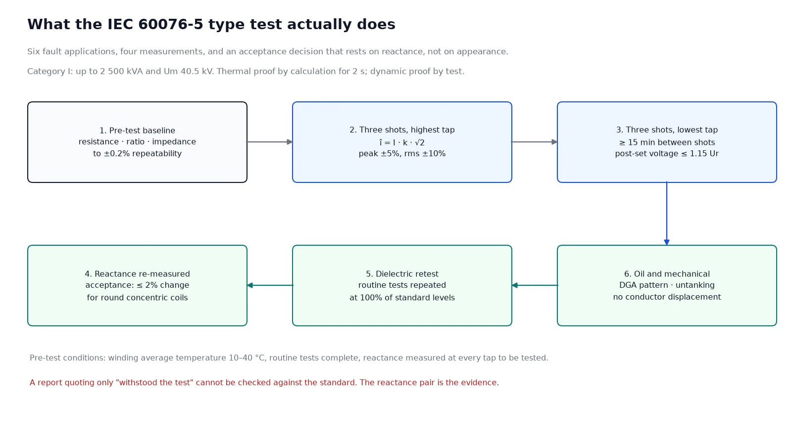
An untanked inspection is part of the acceptance, but it is the weakest criterion, because a winding can be displaced by a fraction of a millimetre and look perfect. The measured criterion is the change in short-circuit reactance before and after the shots. For round concentric windings the change must stay within 2%; non-circular coils are allowed a wider tolerance. That 2% is a sensitive indicator precisely because leakage reactance is a geometric property — a small movement of the winding stack shows up immediately.
| Check | Acceptance | What it catches |
|---|---|---|
| Short-circuit reactance | Within 2% of the pre-test value (round concentric) | Radial or axial winding movement |
| Dielectric routine tests | Repeat at 100% of standard levels | Insulation damage that survived electrically at first |
| No-load loss and current | No significant change | Core displacement, turn-to-turn short |
| Oil DGA after the test | No gas generation pattern | Local overheating or arcing |
| Visual after untanking | No conductor displacement, no spacer movement | Structural damage the electrical tests cannot see |
Two windings can both satisfy the thermal calculation and behave completely differently under the dynamic test. Copper is limited to 250 °C and aluminium to 200 °C, and the reason is not conductivity: at 250 °C copper still retains useful tensile strength, while aluminium creeps and loses shape well before that temperature, so the mechanical failure arrives earlier than the thermal one. In a fault, aluminium also has a higher thermal expansion per unit of temperature rise, which adds to the displacement of the stack — the trade-off is set out in copper versus aluminium windings.
The winding construction matters as much as the material. A layer winding behaves differently from a disc winding, an interleaved or shielded winding changes the impulse distribution at the ends, and a continuously transposed conductor resists axial tilt better than a set of parallel rectangular strands that can slide against each other. When you compare two quotations at the same impedance and the same loss figures, the short-circuit margin is one of the few remaining differences — and it is invisible on the data sheet.
A short-circuit report is only evidence if you can map it onto the unit in your order. Ask for the standard edition used, the category, the tap positions tested, the calculated and achieved peak and rms currents, the pre-test and post-test reactance values with the temperatures at which they were measured, the results of the repeated dielectric tests and the partial discharge figures, and a clear statement about the untanked inspection. A report that gives only “test passed” is a marketing document.
The harder question is equivalence. The report belongs to a design, and “equivalent design” is where specifications quietly diverge from reality: a different winding type, a different clamping structure, a change of conductor supplier or a change from round to rectangular wire all invalidate the equivalence. For a project with high fault levels, the reasonable request is the report plus a written comparison of the tested design against the offered design, item by item, on winding type, conductor, clamping and spacers. The document hierarchy that sits behind the report is in the IEC, IEEE and GB standards map.
| Requirement | Wording that actually protects you |
|---|---|
| Standard and edition | Dynamic and thermal withstand to IEC 60076-5, current edition, Category stated |
| Proof of dynamic ability | Type test report on an equivalent design, issued within the last 10 years, from an accredited laboratory |
| Equivalence | Tested and offered units to share winding type, conductor type, clamping arrangement and spacer material |
| Acceptance | Reactance change within 2% for round concentric windings, full dielectric retest, DGA on oil-filled units |
| System data for the calculation | System fault level and X/R ratio to be supplied by the purchaser; thermal calculation to include system impedance |
IEC 60076-5 proves two different things with two different methods. The thermal claim is arithmetic: a two-second adiabatic calculation against a conductor temperature limit, which most distribution transformers pass with wide margin. The dynamic claim is structural: six fault applications with a controlled first peak, judged by a 2% reactance change and a full dielectric retest. If your project has a high fault level, the dynamic half is the one to interrogate, and the interrogation is not about the report existing — it is about the report describing the winding you are buying. For the upstream calculation that produces the fault current in the first place, see percentage impedance and voltage drop, and for the factory test sequence that follows, the FAT guide covers the routine tests in order.
No. It is a type test on a design, not a routine test on each unit. Every unit gets the routine dielectric tests; the short-circuit proof is inherited from the design test, which is why the equivalence question matters more than the certificate itself.
Thermal is the conductor temperature reached during the fault, limited to 250 °C for copper and 200 °C for aluminium in oil, and it can be proven by calculation. Dynamic is the mechanical stress of the first cycles, limited by winding structure, and it is proven by test.
Because the backup protection sets the worst credible case. If the transformer’s own relay fails, an upstream device may take a second or more, and the winding must survive the same fault for that duration. The two-second figure includes that scenario.
It reduces the fault current and therefore the force, but it also increases voltage drop, losses and the difficulty of coordinating protection. A very high impedance is a design compromise, not a guarantee — the winding still has to be built to carry its own fault current.
It can, but the limit is 200 °C rather than 250 °C and the mechanical behaviour is less forgiving. Above roughly 1 600 kVA at medium voltage, the design discipline needed to make aluminium equivalent usually removes the cost advantage.
The pre-test and post-test reactance values with their measurement temperatures, and the tap positions tested. If those are missing, the report cannot be used to judge anything, however impressive the laboratory letterhead.