Transformer Protection Coordination: Main and Backup
Coordination belongs to a set of relays, not one device. Damage curve, inrush blocking, CT saturation and a worked grading example at 1 000 kVA.
Read More

The transformer BIL figure on a data sheet — 75 kV, 125 kV, 170 kV — is a test level, not a design margin and not a measure of quality. It says that the insulation was subjected to a standard 1.2/50 µs impulse of that peak value and did not break down. What it does not say is whether that level is the right one for your system, and that question is decided somewhere else entirely: by the surge arrester, the length of conductor between the arrester and the transformer, the altitude of the site and the pollution level of the air.
Insulation coordination is the process of choosing a withstand level that sits above the overvoltage the arrester lets through, with a margin. Get the arithmetic wrong in either direction and you either pay for insulation you will never stress, or you buy a transformer whose BIL is lower than the surge that reaches it.
Three numbers travel together on every medium-voltage transformer nameplate, and they are not interchangeable:
| Quantity | Symbol | What it means | How it is verified |
|---|---|---|---|
| Highest voltage for equipment | Um | The maximum line-to-line rms voltage the insulation is rated for, one class above nominal | Design basis, not a test |
| Rated lightning impulse withstand | LI / BIL | Peak voltage of a 1.2/50 µs wave the insulation survives | Impulse test, type and routine |
| Rated short-duration power-frequency withstand | AC | rms voltage held for one minute without breakdown | Applied voltage test, routine |
The pairing is fixed by IEC 60071-1. At Um = 12 kV the standard pair is 28 kV AC and 75 kV LI; at 24 kV it is 50 kV and 125 kV; at 36 kV it is 70 kV and 170 kV. For the 40.5 kV class used widely in Chinese and IEC-derived specifications, the pair is 95 kV AC and 185 kV LI. The two values are related but not proportional — the impulse level grows faster than the power-frequency level, because the impulse stresses the insulation through a capacitive divider rather than through the bulk of the material.
Note that Um is not the nominal system voltage. A 10 kV distribution system has Um = 12 kV, and a 20 kV system has Um = 24 kV. This gap is the single most common source of mis-specified insulation levels in export projects, and the voltage-class differences that cause it are covered in 10 kV versus 11 kV versus 13.8 kV.
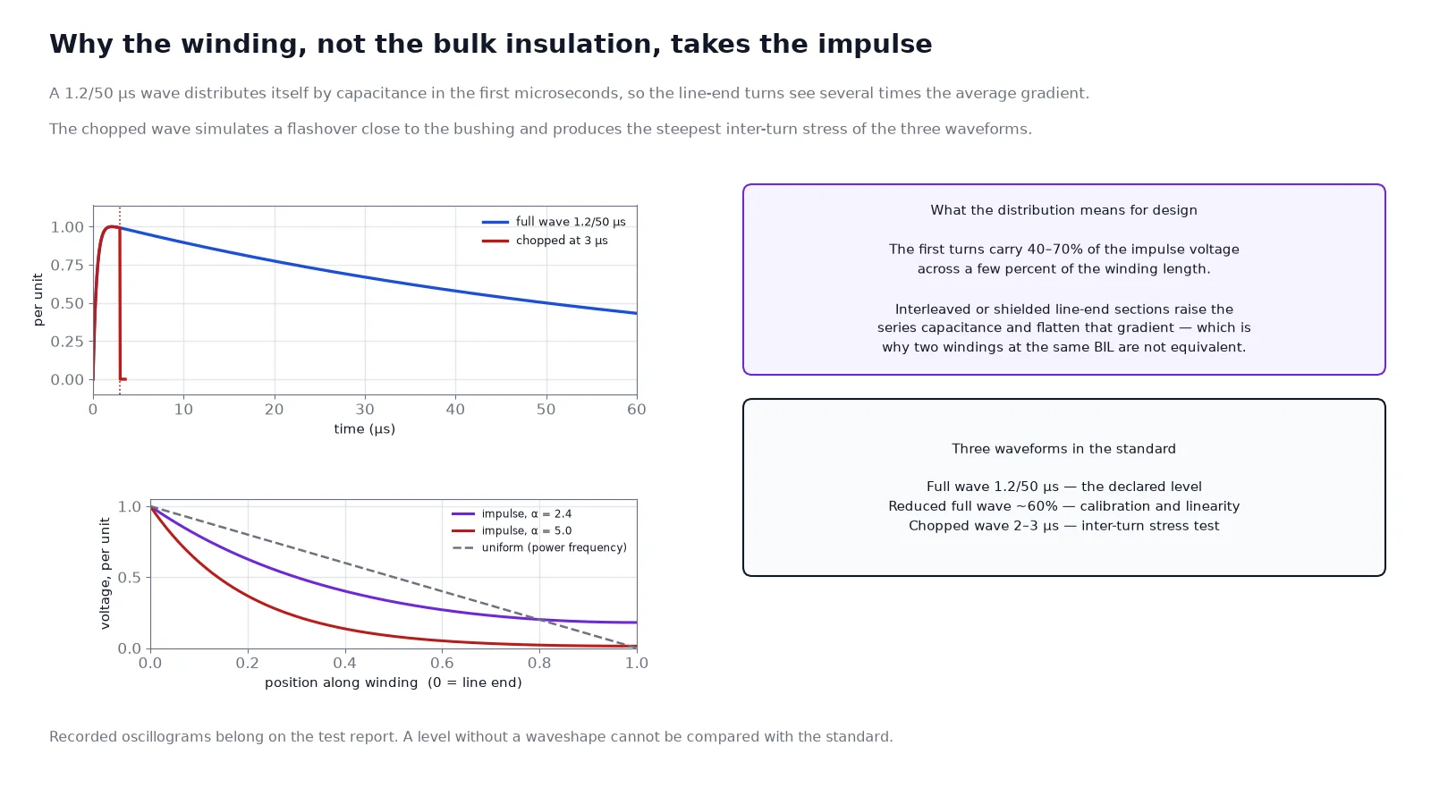
The standard wave rises to peak in 1.2 µs and falls to half value in 50 µs. That shape is a compromise between two physical realities: real lightning currents rise in a few microseconds, and the insulation of a winding responds to the front of the wave through capacitance rather than resistance. A wave that rises this fast distributes itself across the winding according to the capacitance network — turn-to-turn and coil-to-earth — not according to the number of turns.
The practical consequence is that the first turns of the line-end coil see a much higher voltage gradient than the average, often several times the gradient during a power-frequency test. Two additional waveforms appear in transformer standards: the chopped wave, which simulates a flashover at the bushing a few microseconds into the impulse and produces a very steep collapse, and the reduced full wave, applied at about 50–75% of the level first, to calibrate the measuring circuit and to confirm that the winding behaves linearly before the full level is applied.
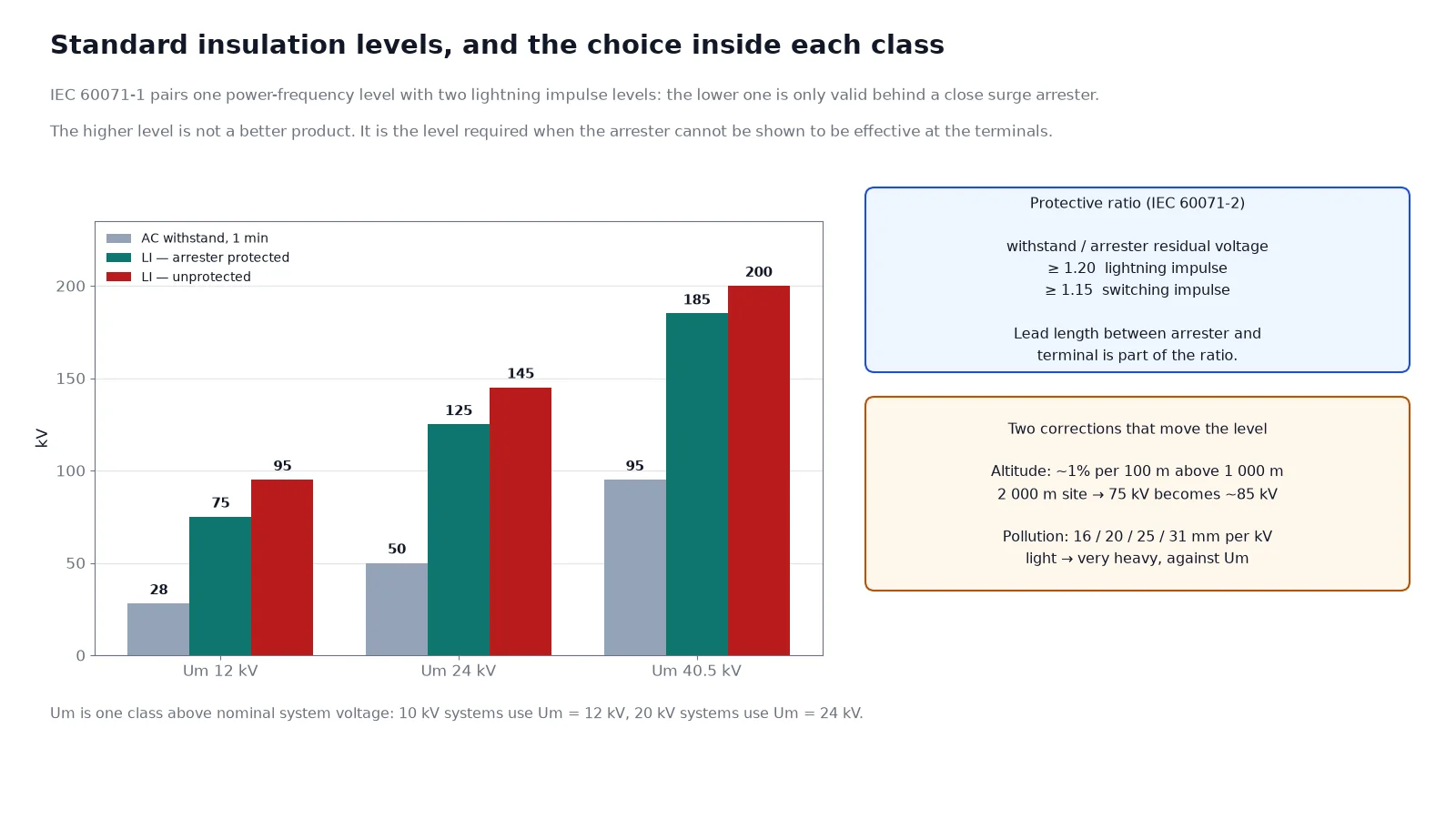
IEC 60071-1 offers two levels for most classes: a common value and an alternative. At Um = 12 kV that is 75 kV or 95 kV; at 24 kV, 125 kV or 145 kV; at 36 kV, 170 kV or 200 kV. IEC 60071-2 states the rule that selects between them: equipment protected by close surge arresters may use the lower value, and equipment not effectively protected must use the higher value. The operative word is “effectively”.
| Um (kV) | AC withstand, 1 min (kV) | LI — arrester protected (kV) | LI — unprotected (kV) | Typical use of the higher level |
|---|---|---|---|---|
| 7.2 | 20 | 40 | 60 | Long overhead feed, no arrester at the terminals |
| 12 | 28 | 75 | 95 | Overhead line entry, coastal exposure |
| 24 | 50 | 125 | 145 | Overhead section longer than a few hundred metres |
| 36 / 40.5 | 70 / 95 | 170 | 185–200 | Substation at the end of an exposed line |
“Effectively protected” is a distance criterion as much as an equipment criterion. An arrester mounted ten metres of cable away from the transformer terminal is installed but may not be effective, because the surge reflects at the transformer and the voltage at the terminal can rise above the arrester’s residual voltage. The protective ratio closes the argument: the withstand level divided by the residual voltage at the equipment must stay above 1.20 for lightning impulses and above 1.15 for switching impulses on non-self-restoring insulation.
Altitude first. Air insulation strength falls with height because the density falls. IEC 60071-2 applies a correction factor to the required withstand voltage above 1 000 m, and for lightning impulses the exponent is unity: at 2 000 m the factor is roughly 1.13, so a 75 kV requirement becomes about 85 kV of required strength at site. Two ways to meet it: specify the next BIL class up, or accept the altitude correction on the test level and let the factory test at the corrected value. Most projects take the first route because it is unambiguous.
Pollution second. Creepage distance is selected by site pollution severity — roughly 16 mm/kV for light, 20 mm/kV for medium, 25 mm/kV for heavy and 31 mm/kV for very heavy, expressed against the highest phase-to-phase voltage for the bushing. A coastal or cement-plant site moves a standard 12 kV design from 20 mm/kV to 25 mm/kV, which changes the creepage from about 240 mm to 300 mm and therefore the bushing length, the phase spacing and the tank dimensions. This is a cost driver, and it belongs in the RFQ rather than in a post-award clarification.
Clearance third. Inside a dry-type transformer the impulse level is held by air and cast resin rather than by oil, and the air clearances that correspond to each BIL are fixed by standard tables: 60 mm at 75 kV, 90 mm at 125 kV, 160 mm at 170 kV, 220 mm at 185 kV for a rod-plane arrangement. When the enclosure is compact, those clearances set the physical size and can push a design into the next frame — which is one of the reasons two 1 600 kVA dry-type units at the same BIL can differ substantially in footprint. The enclosure contribution is covered in IP rating and enclosure selection.
For an oil-immersed transformer, the impulse stress is shared between oil gaps and solid insulation, and the oil volume gives a good self-restoring margin between the winding and the tank. For a cast-resin dry-type transformer, the winding insulation is a solid composite with the conductor cast inside it, and the external insulation is air. The failure mode therefore shifts: partial discharge inside the casting is the dominant long-term risk, and it does not self-heal.
This is why a dry-type unit at the same BIL usually carries an explicit partial discharge limit at a specified voltage, typically 10 pC at 1.1 times rated phase-to-earth voltage, and why the impulse test on a cast-resin winding is followed by a PD measurement rather than by a visual check alone. A cast-resin transformer that passes the impulse test but shows elevated PD has effectively failed, even though the BIL number was met. The mechanism is described further in partial discharge in cast-resin transformers.
| Specification item | What to write |
|---|---|
| Insulation level basis | Um, LI and AC levels to IEC 60071-1, with the chosen alternative stated explicitly |
| Arrester coordination | Arrester type, Uc, residual voltage, mounting distance from the transformer terminal |
| Altitude | Site elevation, with correction applied per IEC 60071-2 if above 1 000 m |
| Pollution | Site pollution severity class and minimum creepage in mm/kV |
| Dry type only | PD limit in pC at a stated voltage, measured after the impulse test |
| Report | Impulse waveshape as recorded, level applied, reduced full wave result, PD figures, tap position tested |
On the report, the two lines worth checking are the recorded waveshape and the reduced full wave result. A report that quotes only “withstood 75 kV” without the oscillogram cannot be compared against the standard, and a winding that behaved non-linearly on the reduced wave is telling you something about the insulation before the full level was ever applied. The wider document set for dielectric testing sits inside the IEC, IEEE and GB standard map.
BIL is the answer to a question that your system asks, not a property the transformer chooses. Fix Um first, select the arrester and its residual voltage second, prove the protective ratio is above 1.20 at the transformer terminals with the real lead length, then check whether altitude and pollution move the requirement. The lower of the two standard levels is legitimate — but only when the arrester is close enough to be effective, and that distance is measured in metres of cable, not in intent. For the specification side of the same conversation, see dry-type transformer specification and insulation class and temperature rise.
Not automatically. A higher BIL costs money in clearances, bushings and tank size, and buys nothing if the arrester already limits the surge well below the lower level. It becomes necessary when the arrester is far from the transformer or absent.
Yes, when Um = 12 kV and the transformer is protected by a close-coupled arrester with the protective ratio verified. If the feed is a long overhead line with the arrester at the upstream switchgear, 95 kV is the safer specification.
Because the two tests stress the insulation differently. The AC test stresses the bulk of the insulation through resistive and capacitive current, while the impulse distributes itself across the winding by capacitance and concentrates at the line end.
It simulates a flashover close to the transformer, which produces a much steeper voltage collapse than a full wave. The resulting inter-turn stress is higher, and some specifications require it for units above a certain voltage class.
Above 1 000 m the required withstand rises by roughly 1% per 100 m for lightning impulses. At 2 000 m that is about 13%, enough to move a 75 kV requirement into the 95 kV class.
The LV winding has its own, much lower, insulation level and is tested with a separate impulse or a higher induced voltage. The BIL on the nameplate refers to the HV winding unless stated otherwise.