Transformer Protection Coordination: Main and Backup
Coordination belongs to a set of relays, not one device. Damage curve, inrush blocking, CT saturation and a worked grading example at 1 000 kVA.
Read More

A k factor transformer exists because a nameplate kVA is calculated for a sinusoidal current that most modern loads no longer draw. A 750 kVA dry-type unit feeding six-pulse drives can sit at 62% of nameplate on the panel ammeter and still run its winding hot spot past 150 °C, because the ammeter measures rms current and the winding heats on something closer to the square of frequency. The K-rating is the number that quantifies the difference, and choosing it correctly is the difference between a twenty-year transformer and a two-year one.
This article covers where the extra heat physically comes from, how the K value is computed from a measured spectrum, what the classes mean in practice, and the decision most projects actually face: buy a K-rated unit, or derate a standard one.
Load loss in a transformer has two parts. The I²R part depends on rms current and is indifferent to waveform. The eddy-current and stray part does not: it depends on the rate of change of flux inside the conductor, so it rises with the square of frequency. A 5th harmonic at 300 Hz in a 60 Hz system produces about 25 times the eddy loss of the same magnitude of fundamental current; the 7th produces 49 times; the 13th produces 169 times.
Those losses do not spread evenly. Skin effect pushes harmonic current to the outer surface of the conductor, and proximity effect pushes it into the faces that sit next to another conductor carrying current in the opposite direction. The result is a local hot spot that a resistance measurement or an rms ammeter will never reveal, while the average winding temperature looks acceptable. Insulation life roughly halves for every additional 10 °C at the hot spot, which is why the failure arrives years before the loading calculation suggested it would.
UL 1561 and the method in IEEE C57.110 define the K-factor as:
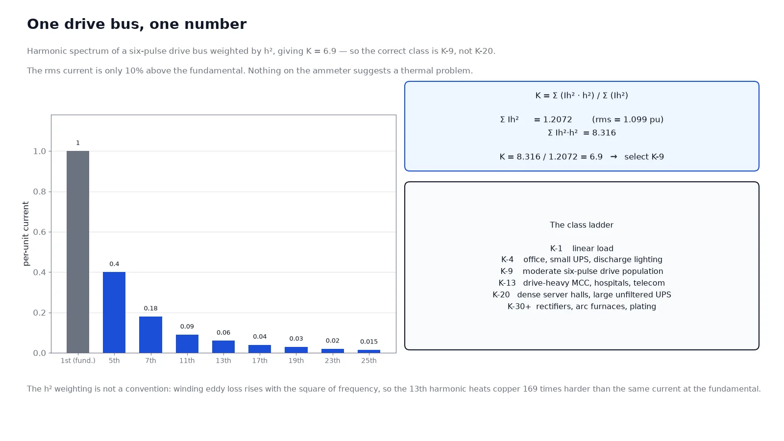
K = Σ(Ih² × h²) / Σ(Ih²)
where Ih is the rms current at harmonic order h, expressed per unit of rated rms load current, and the sum runs over all harmonic orders including the fundamental. A pure sine wave gives K = 1. Each harmonic is weighted by the square of its order, which mirrors the physics: the loss penalty is exactly the frequency-squared term.
| Harmonic order | Per-unit current | Ih² | Ih² × h² |
|---|---|---|---|
| 1 | 1.000 | 1.0000 | 1.000 |
| 5 | 0.400 | 0.1600 | 4.000 |
| 7 | 0.180 | 0.0324 | 1.588 |
| 11 | 0.090 | 0.0081 | 0.980 |
| 13 | 0.060 | 0.0036 | 0.608 |
| 17 | 0.040 | 0.0016 | 0.462 |
| 19–25 | 0.075 total | 0.0031 | 0.677 |
| Total | rms 1.099 | 1.2072 | 8.316 |
K = 8.316 / 1.2072 = 6.9, so the correct class is the first one at or above the calculated value, K-9. Note two things about this result. The total rms current is only 10% above the fundamental, which is why the ammeter looks reassuring. And a 6-pulse drive bus with a 45% current THD lands at K-9, not K-20 — a common over-specification in industrial projects.
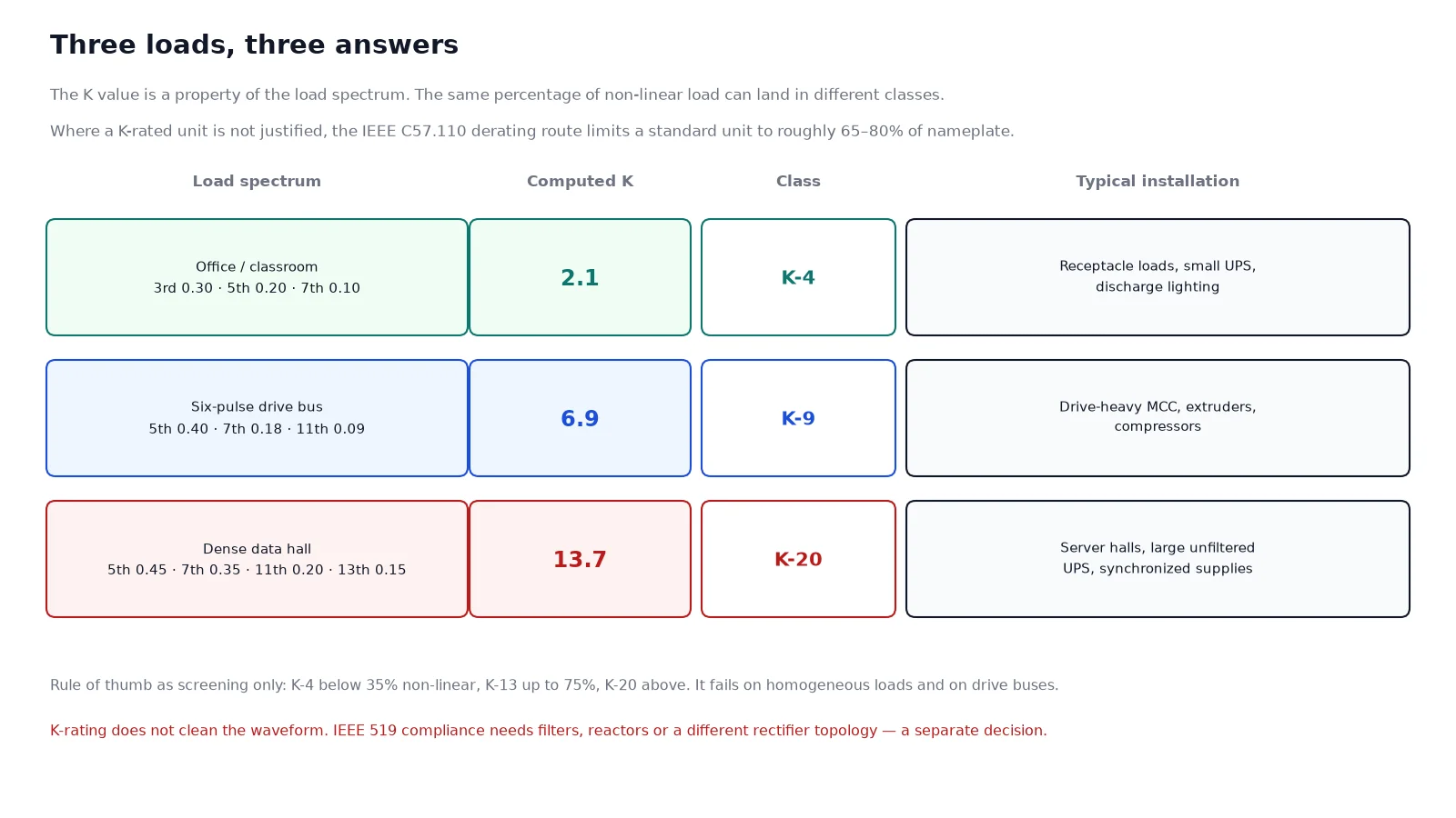
Two loads can both report 40% current THD and require different transformers. A spectrum concentrated in the 5th and 7th produces a moderate K; a spectrum of the same total distortion concentrated in the 11th, 13th and higher orders produces a much larger one, because the weighting is h². This is why the percentage-of-non-linear-load rule of thumb — K-4 below 35%, K-13 up to 75%, K-20 above — is a screening heuristic, not engineering. It happens to work on office and classroom loads, where the spectrum is dominated by switch-mode supplies with a similar signature, and it fails on drive-heavy buses and on data halls.
The engineering answer is to measure or model the spectrum. A power-quality survey on an existing board takes an afternoon. On a new design, the drive manufacturer’s harmonic data plus the IEEE 519 study that most projects already require will produce the numbers you need.
| Class | Computed K value it covers | Typical load |
|---|---|---|
| K-1 | Linear | Motors, resistive heating, incandescent lighting |
| K-4 | Up to 4 | Office and school receptacle loads, small UPS, discharge lighting |
| K-9 | Up to 9 | Moderate six-pulse drive population, mixed commercial with drives |
| K-13 | Up to 13 | Drive-heavy MCCs, extruders, compressors, hospitals, telecom rooms |
| K-20 | Up to 20 | Dense server halls, large UPS without input filtering, multiple VFD banks |
| K-30 to K-50 | Above 20 | Arc furnaces, plating rectifiers, electrolytic loads |
The class is a withstand rating, not a filter specification. A K-13 transformer does not reduce harmonic current, does not improve the waveform and does not help you pass an IEEE 519 limit at the point of common coupling. It survives the spectrum; the spectrum is unchanged. If the design problem is “the transformer keeps failing”, the K-rating is the answer. If the problem is “we cannot pass the harmonic compliance test”, it is not.
| Design change | What it buys |
|---|---|
| Parallel or transposed stranded conductor | Lower eddy loss in the winding by breaking up the conductor cross-section |
| Reduced flux density, larger core | Lower peak flux and more thermal mass; typically one frame size up |
| Oversized neutral, commonly 200% | Carries additive triplen current without overheating the neutral bar |
| Additional cooling ducts | Removes the extra heat from between coil layers rather than through them |
| Class H (180 °C) or Class R (220 °C) insulation | Thermal margin at the hot spot, not merely a higher nameplate class |
| Electrostatic shield | Reduces transfer of common-mode noise to the secondary, not harmonic loss |
These changes explain the price and the size penalty: a K-20 unit is usually one frame larger than a standard transformer of the same kVA, which matters when the electrical room was dimensioned before the load was known. The relationship between frame size, losses and heat rejection is covered in efficiency class and loss evaluation.
IEEE C57.110 provides the other legitimate route. Instead of buying a reinforced transformer, you calculate the maximum load a standard unit can carry with the measured spectrum while keeping its hot spot inside the insulation rating. The output is a derating factor, and it is often severe: a standard dry-type unit under a drive-heavy spectrum can be limited to 65–75% of nameplate, and in bad cases below that.
| K-rated unit | Derated standard unit | |
|---|---|---|
| Capacity available to the load | Full nameplate kVA | Nameplate × derating factor, often 0.65–0.80 |
| Neutral | Sized for triplen current, typically 200% | Standard neutral, may become the weak point |
| Capital cost | Higher per kVA | Lower per kVA, but you may need a larger unit |
| Best case | Dense, predictable harmonic load | Modest harmonic content, spare capacity already exists |
The choice is arithmetic, not principle. If a 1 000 kVA standard unit derated to 70% still covers the real load with margin, buying a 1 000 kVA K-13 instead is money spent on capability that will never be used. If the load is fixed and dense, the derating route usually ends up buying a physically larger standard transformer than the K-rated one you avoided.
Triplen harmonics — the 3rd, 9th, 15th — are zero sequence. In a four-wire wye system they do not cancel between phases; they add in the neutral. With a heavily non-linear single-phase load, the neutral current can approach or exceed the phase current, and a neutral bar sized at 100% of phase current becomes the hottest conductor in the system. K-rated transformers ship with an oversized neutral for this reason, but the feeder neutral downstream is frequently still 100%, and that is where the failure occurs.
The winding connection matters too: a delta primary traps triplen current and prevents it from reaching the upstream network, which is one reason a delta-wye K-rated unit is the usual choice on a drive bus. If your transformer is wye-wye, the triplen path continues upstream and the whole distribution design needs to be re-examined.
Two load types concentrate harmonics hard enough that the K-rating is no longer optional. The first is a drive-dense industrial MCC, where several six-pulse drives run simultaneously and their 5th and 7th components reinforce rather than cancel. The second is the modern data hall, where thousands of identical switch-mode supplies operate in lockstep with no load diversity; the spectrum is homogeneous and continuous, which is what pushes a design from K-13 into K-20. That case is examined in transformers for data centers. Solar and battery inverters produce a different signature again — switching frequencies well above the 50th harmonic plus a DC component on some topologies — and the selection logic there is in transformers for solar PV and BESS.
The full electrical data set for this comparison, including loss figures at non-linear load, belongs in the technical data sheet, and the mechanical and enclosure constraints are set out in the dry-type specification guide.
K is a load property, not a transformer property, and it is computed from the harmonic spectrum with each order weighted by its square. A typical six-pulse drive bus lands near K-7 and needs K-9; a dense data hall lands higher and needs K-20. The rating does not clean the waveform — it makes the winding survive it through transposed conductor, lower flux density, more cooling and an oversized neutral. The genuine alternative is to derate a standard unit by the IEEE C57.110 method, which is cheaper only when the derated capacity still covers the load. The catalogue range for this construction is in dry-type power transformers.
No. The class is a thermal withstand rating for a spectrum; a lower class under a heavier spectrum runs the hot spot above its insulation limit, and the failure is gradual rather than immediate.
No. It has no filtering action. Harmonic current downstream and upstream is unchanged, and compliance with IEEE 519 still requires filters, reactors or a different rectifier topology.
The calculation is the same and IEEE C57.110 covers liquid-immersed units, but the K-rating itself is a UL 1561 dry-type designation. For oil-filled units the equivalent requirement is usually written as a harmonic loss factor or a specified non-linear load capability.
Because triplen harmonic currents add in the neutral instead of cancelling. In a four-wire system with switch-mode loads the neutral current can approach or exceed phase current, and a 100% neutral becomes the limiting conductor.
From the drive and UPS manufacturer’s harmonic data, combined with the load schedule and the diversity assumptions in the harmonic study. Where that study is not available, a conservative spectrum based on the planned rectifier topology is better than a percentage rule of thumb.
Usually slightly less at the same load, because lower flux density and larger conductor cross-section reduce losses. The purchase price is higher; the operating cost is not, provided the unit is not grossly over-specified.