A transformer hums because its core changes length. That is not a metaphor: the electrical steel expands very slightly along the flux path on every half cycle, so a unit on a 50 Hz supply vibrates at 100 Hz and one on 60 Hz vibrates at 120 Hz. Everything audible about transformer noise follows from that mechanical fact, plus the structure it is bolted to.
This matters commercially because noise has moved from a nuisance to a specification item. A unit that would be unremarkable in an industrial yard is unacceptable above a hospital ward, a hotel floor or a metro platform. The enquiry increasingly carries a dB(A) limit at a stated distance, and that limit is not achievable by choosing a quieter-sounding brand — it is achieved by designing for it, mounting for it and, if necessary, enclosing for it.
Where the sound actually comes from
Four sources contribute, and separating them decides which fix will work.
- Magnetostriction in the core. The dominant source at no load, at twice the supply frequency, with harmonics at 4× and 6×. It depends on the flux density and on the steel; reducing either reduces it.
- Winding vibration. Current-carrying conductors in a leakage field experience forces at twice the frequency. It grows with load current and becomes significant at high current density.
- Clamping and structure. Loose laminations, a slack core bolt or a tank panel with a resonance near 100 Hz radiates far more than the core alone.
- Auxiliaries. Fans and oil pumps on forced-cooled units, which produce broadband noise and are often louder than the core at close range.
The practical consequence: if the noise is present with the transformer energised but unloaded, it is core. If it rises with load, it is winding or tank. If it starts when a fan stage cuts in, it is the fan.
What the standards allow
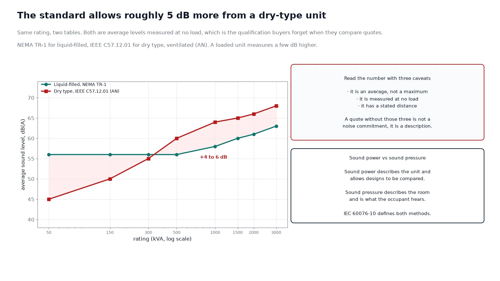
Two tables govern most specifications. NEMA TR-1 covers liquid-filled units and IEEE C57.12.01 covers dry type; both are average sound levels, measured at no load unless stated otherwise, and both rise with rating.
| Rating, kVA |
Liquid-filled, self-cooled, NEMA TR-1 dB(A) |
Dry type, ventilated (AN), IEEE C57.12.01 dB(A) |
| Up to 50 |
56 (up to 500 kVA) |
40 to 45 |
| 51–150 |
56 |
50 |
| 151–300 |
56 |
55 |
| 301–500 |
56 |
60 |
| 501–700 |
57 |
62 |
| 701–1,000 |
58 |
64 |
| 1,001–1,500 |
60 |
65 |
| 1,501–2,000 |
61 |
66 |
| 2,001–3,000 |
63 |
68 |
Three qualifications change how these numbers should be read. They are average levels, not maxima, so half of production units are louder. They are measured at no load, so a loaded unit will be a few dB higher. And they are sound pressure at a defined distance, which means the same unit measured at 0.3 m and at 3 m gives two very different numbers — always state the distance and the standard with the figure.
IEC 60076-10 defines the measurement itself: the sound pressure method for a specified contour, and the sound power method for determining the unit’s output independent of the room. Sound power is the number to use when comparing designs; sound pressure is the number that matters at the nearest occupied room.
Why load and harmonics raise it
A transformer quoted at 58 dB(A) at no load will not measure 58 dB(A) at full load. Two effects add to it: winding vibration, which scales with current, and a slight increase in core flux distortion from the load current’s harmonic content. Expect a few dB, more on a unit with a high current density.
Harmonics are the larger effect on modern networks. Each harmonic component drives its own magnetostrictive response, so a load with 30 % current THD produces audible components at 200 Hz, 300 Hz and higher on top of the fundamental 100 Hz. The result is not just louder but harsher — a tonal hum plus a buzz — and it is the reason a data centre or a drive-fed plant needs a noise figure quoted at realistic harmonic conditions rather than at sinusoidal no load.
Airborne and structure-borne paths
Half the noise problems in buildings are not the transformer. They are the path.
Airborne sound leaves the enclosure and travels through the room, the door, the louvre and any penetration. Structure-borne vibration leaves through the mounting feet, the earth bar and the cable conduit, and re-radiates from the floor slab or the wall in a different room — sometimes several floors away, and often louder there than in the plant room. When a complaint comes from an office two floors up while the plant room itself seems acceptable, the path is structural, and no amount of acoustic lining in the plant room will fix it.
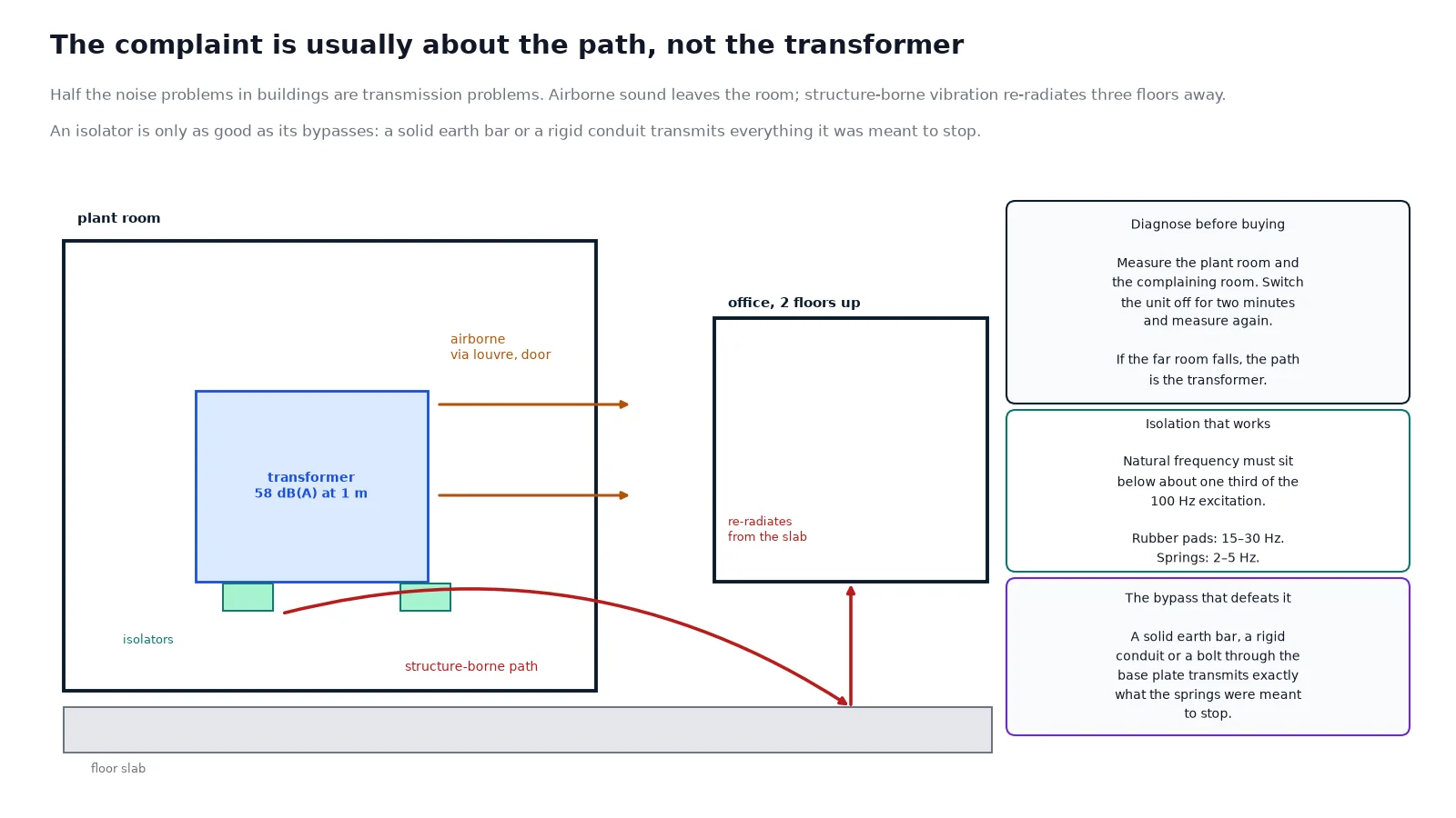
The diagnostic is simple and worth doing before any purchase: measure in the plant room and in the complaining room, then switch the transformer off for two minutes and measure again. If the level in the far room falls when the transformer is off, it is transformer-borne; if it does not, the source is elsewhere.
Reducing noise at the source
Source measures are the cheapest per decibel, because they are designed in rather than added. Six are worth specifying.
- Lower flux density. Running the core at 1.4–1.5 T instead of 1.6–1.7 T cuts magnetostriction noticeably, at the cost of a larger core and more material. This is the single most effective design lever.
- Step-lap or mitered core joints. Better flux transfer at the joint means less local vibration than a butt joint.
- Core clamping and tie rods. A properly clamped core behaves as one mass; a loose one behaves as a set of independent laminations.
- Resin or VPI encapsulation. A cast-resin winding is stiffer and radiates less winding noise than an open-wound one, though the resin itself can act as a drumhead if the design is poor. It is one of the reasons cast-resin dry-type units dominate indoor plant rooms despite the higher cost.
- Tank stiffening. On liquid units, stiffeners and a thicker tank wall move panel resonances away from 100 Hz.
- Low-speed fans and pump selection. On forced-cooled units, fan noise often dominates; a larger, slower fan at the same airflow is quieter.
The trap is assuming that a low-loss core is automatically a quiet one. Amorphous metal cuts no-load loss by roughly 60–70 %, but its magnetostriction is not lower, and amorphous units have historically measured a few dB louder than grain-oriented silicon steel at the same flux density. A quiet amorphous transformer is a design achievement, not a property of the material — see our note on amorphous dry-type transformers for where that trade actually pays.
Enclosure and room acoustics
Once the source is as quiet as the budget allows, the enclosure and the room do the rest. A standard IP23 sheet-steel enclosure attenuates very little; a purpose-designed acoustic enclosure with absorptive lining and a baffled ventilated path can take 10–20 dB(A) out of the radiated level, at the cost of heat retention — which then needs its own airflow calculation, because a quiet transformer that overheats is not a solution.
Room measures that cost almost nothing:
- Do not put the unit in a corner. Two reflective walls close to the source add several dB at the receiver.
- Keep the unit away from thin plasterboard partitions; mass is what stops low-frequency sound, and 100 Hz passes through lightweight walls easily.
- Treat the plant room’s own surfaces if the room is reverberant, and seal the door — a louvred door with no acoustic rating is an open window.
- Route cables and earth connections flexibly, so the structure-borne path is broken at the unit rather than at the far end of the building.
For buildings where the transformer sits near occupied space, the application note on transformers for commercial buildings sets out the room and siting logic, and metro and tunnel installations have their own constraints in our note on metro and underground substations.
Vibration isolation that actually works
Isolation is a resonance problem, and it fails when the isolator’s natural frequency is too close to the excitation frequency. The rule of thumb: the isolator’s natural frequency should be no more than about one third of the lowest excitation frequency. With a 100 Hz fundamental, that means a natural frequency of roughly 10–15 Hz or below, which is beyond a plain rubber pad.
| Isolator |
Typical natural frequency |
Where it fits |
Failure mode |
| Neoprene or cork pad |
15–30 Hz |
Small units, low-risk locations, minor improvement |
Too stiff to isolate 100 Hz well; creeps and hardens with age |
| Rubber-to-metal mount |
8–15 Hz |
Distribution units on a concrete slab |
Over-compressed if undersized; short-circuited by a solid earth strap |
| Steel spring isolator |
2–5 Hz |
Large units, plant rooms above occupied space |
Needs a seismic restraint and a flexible connector, or it is bypassed |
| Inertia base plus springs |
3–5 Hz |
Where structure-borne noise is the complaint |
Adds height and weight; must be designed, not improvised |
An isolator is only as good as its bypasses. A solid earth bar, a rigid conduit, a hard-piped cable tray or a bolt through the base plate will transmit everything the isolator was meant to stop. Flexible braids, a flexible conduit section and a resilient pipe coupling are part of the isolation, not accessories.
Measuring it properly
Noise complaints are usually settled by measurement, and bad measurement is why they are sometimes settled wrongly.
- Measure at the specified distance and height, and state both. A reading at the enclosure surface is not comparable with one at 1 m.
- Measure background first, then the unit. If the background is within 3 dB of the total, the result is not usable; if it is 3–10 dB below, apply the correction; above 10 dB, no correction is needed.
- Use A-weighting for the complaint and consider the tonal content separately. A unit that meets its dB(A) limit but has a strong 100 Hz tone will still generate complaints, because low-frequency tones are judged more annoying at equal loudness.
- Record the load at the time of measurement. A no-load figure compared against a loaded complaint is not a comparison.
Normal hum or a developing fault?
Not every noise is a design problem. Some sounds are information, and the change in sound is more diagnostic than the level.
| Sound |
Likely cause |
Action |
| Steady 100 or 120 Hz hum, constant |
Normal magnetostriction |
None; address the path if it is a nuisance |
| Hum that rises with load |
Winding vibration, or harmonic load |
Check harmonic content and current density |
| Harsh buzz with a tonal edge |
Harmonic flux components |
Measure THD; consider a K-rated or derated unit |
| Rattle or intermittent clatter |
Loose laminations, clamp or panel |
Inspect and re-torque at the next outage |
| Crackling or sizzling |
Partial discharge or a bad connection |
Investigate promptly; do not defer |
| Banging or thumping |
Loose winding or core, or a through-fault effect |
De-energise and inspect |
| Sudden increase in level |
Core saturation, DC offset, fan fault, resonance change |
Compare load, voltage and harmonic record |
The pattern to watch is change. A transformer that has hummed at the same level for a decade is behaving; one that has become noticeably louder in a month is telling you something, and the answer is rarely “it is just noisy now”.
Frequently asked questions
What is a normal transformer noise level in dB?
For a liquid-filled distribution unit, NEMA TR-1 allows about 56 dB(A) up to 500 kVA and 58 dB(A) at 1,000 kVA. A dry-type unit at the same rating is typically 60–64 dB(A). These are average levels at no load, so a loaded unit will measure a few dB higher.
Why is a transformer louder at night?
Because the background is quieter, not because the transformer changes. At night the ambient in a residential area can drop by 15 dB(A), so the same unit becomes the dominant source. Load also tends to fall, which slightly reduces the winding contribution but leaves the core hum unchanged.
Can transformer noise be reduced after installation?
Partly. Isolation mounts, flexible connections, an acoustic enclosure, sealing the plant-room door and moving the unit away from a corner all help. What cannot be changed after the fact is the core’s flux density, which is where most of the noise originates — that is a purchase decision.
Does a low-noise transformer cost more?
Yes, typically 10–20 % for a design with reduced flux density and improved clamping. It is usually cheaper than the alternatives: an acoustic enclosure, a civil modification, or a planning dispute with a neighbour. Specifying the limit at the enquiry stage is the low-cost route.
What causes a transformer to hum louder than usual?
Overvoltage or core saturation, harmonic load current, a loose lamination or clamp, a failing fan bearing, or a resonance in the tank or the mounting structure. A sudden change with no load change usually points to the core or the structure rather than to the electrical duty.
Is a dry-type transformer noisier than an oil-filled one?
At the same rating, usually yes — the standard allows roughly 4–6 dB(A) more, because there is no oil to damp the core and no tank to contain the sound. The gap narrows with good encapsulation and disappears with an acoustic enclosure.
The takeaway
Noise is a design variable, not a brand property. Decide the limit at the enquiry, state the distance and the standard, and buy a core designed for it — a 10–20 % premium at the order stage is almost always cheaper than the enclosure, the civil work or the complaint that follows. Then treat the installation as part of the acoustic design: isolation that is not short-circuited, a room that does not amplify, and a door that closes properly.
If a project has a noise limit to meet, send us the rating, the distance and the dB(A) target, together with the room dimensions. We will tell you whether the limit is achievable from the core alone, what enclosure or isolation is needed to reach it, and which of the two is the cheaper route in your building. The mechanical envelope for each rating is on our dry-type size chart, and cooling arrangements that affect fan noise are covered under ONAN and ONAF cooling.