Every winding temperature monitoring scheme on a transformer reduces to one question that the drawing rarely answers: where exactly is the sensor, and what is it actually touching? A controller showing 82 °C tells you nothing until you know whether that 82 °C came from a PT100 buried inside the low-voltage winding, from a probe sitting in the top oil, or from a pocket welded to the tank wall. Those three readings can differ by 40 K on the same unit at the same moment, and only one of them ages insulation.
This guide is about the hardware and the settings rather than the theory of heat transfer. It covers what the hot spot is and why it is not the average winding temperature, which sensor types can see it, how to wire an RTD so it still reads correctly after ten years in a plant room, what the fan, alarm and trip thresholds should be for each insulation class, and how to test the whole chain at commissioning so that the trip output actually opens the breaker.
Three temperatures, and only one of them decides insulation life
A transformer has a temperature distribution, not a temperature. The top oil is the warmest oil, because oil rises through the winding and collects under the cover. The average winding temperature is what the resistance measurement gives you. The hot spot is the small region near the top of the winding, on the inner surface close to the core, where the copper is hottest and the oil flow is worst. It is typically 10 to 25 K above the average, depending on winding height and duct design.
Insulation ageing is an Arrhenius process, which means it responds to the local temperature at the hottest point, not to an average. That is why the standards define three separate limits and why applying one to the other is the most common setting error in the field.
| Quantity |
What it describes |
Typical rise limit, oil-immersed |
How it is obtained |
| Top-oil temperature |
Warmest oil, under the cover |
60 K (IEC 60076-2) |
Direct bulb or PT100 in the top oil |
| Average winding |
Mean copper temperature |
65 K (IEC 60076-2) |
Winding resistance measurement, or calculated |
| Hot spot |
Hottest copper, near the top of the winding |
78 K (IEC 60076-2), 80 K (IEEE C57.12.00) |
Direct fibre-optic sensor, or thermal model |
For dry-type units the structure is different again. IEC 60076-11 states the permissible average winding rise against the insulation class rather than against a single oil figure: 80 K for class 130 (B), 100 K for class 155 (F), 125 K for class 180 (H), measured with a 40 °C maximum ambient. A class F casting is therefore expected to sit at roughly 140 °C at rated load in a 40 °C room, with 15 K of headroom to the 155 °C class temperature. That 155 °C figure is the one the trip setting has to respect, and the relationship between class and rise is set out in insulation class and temperature rise.
Which sensor can actually see the hot spot
Four technologies are in common use, and they are not interchangeable. The difference is not accuracy on the bench — it is whether the sensor is in the winding or next to it.
| Sensor |
Where it sits |
Accuracy |
Can it be retrofitted? |
| PT100 embedded in the winding |
Cast or pressed into the LV winding during manufacture, usually two per phase |
Class A: ±0.45 K at 150 °C |
No — the pocket must exist from the start |
| PT100 in a tank pocket |
Welded pocket in the tank wall or cover |
Same as above, but measures the pocket |
Yes |
| PTC or bimetal switch |
Winding surface or busbar |
Switching point only, no reading |
Yes |
| Fibre-optic probe |
Inside the winding, between conductor layers |
±1 K over −40 to +250 °C |
No — fitted before impregnation |
The fibre-optic probe is the only one that measures the hot spot directly rather than inferring it. It is a gallium-arsenide crystal on the end of a fibre, interrogated optically, so there is no metal in the winding, no electromagnetic interference, and no drift from lead resistance. On units where loading is close to the limit for most of the year — traction, arc furnaces, data-centre duty — two to four probes distributed along the winding height are the only way to know the real margin. The alternative is the thermal model discussed below, which is a calculation, not a measurement, and inherits every assumption in it.
The cast-resin case deserves a note. Because the winding is cast, an embedded PT100 cannot be replaced, and a pocket that was cast in the wrong place is a permanent error. Two probes per phase, one at the top of the winding and one mid-height in the duct, give both a hot-spot indication and a check on the temperature gradient — if the top probe is not warmer than the middle one under load, the probes are not where the drawing says they are. On a cast-resin 10 kV dry-type transformer the probe pockets are part of the mould, so the arrangement is fixed at the design stage and cannot be negotiated at commissioning.
Getting the signal to the controller intact
A PT100 is 100 Ω at 0 °C with a slope of 0.385 Ω per kelvin. That slope is the weakness: one ohm of unwanted lead resistance reads as 2.6 K of extra temperature, and a 40 m run of 1.5 mm² copper is already about 0.9 Ω. A two-wire connection turns lead resistance straight into a positive temperature offset that grows with cable length and never appears on any drawing.
Use three-wire connections as a minimum, four-wire where the run exceeds about 50 m or the reading is used for anything other than an alarm. Keep the excitation current below 1 mA so the element does not self-heat, and use shielded twisted pair with the shield grounded at the controller end only — grounding both ends creates a loop that will pick up the very switching noise the shield was meant to exclude. Route the RTD cable at least 300 mm from the MV conductors, and cross rather than run parallel when they must meet.
Then decide what the controller should do when a wire breaks. This is the setting that is most often left at the factory default. A break in a PT100 circuit drives the reading upward, toward the top of the scale, which looks exactly like an overheating winding. If the controller treats it as an over-temperature, a loose terminal trips the plant. The correct behaviour is to annunciate a sensor fault, inhibit the temperature trip for that channel, and keep running on the remaining two — which requires the controller to have a separate sensor-fault output and a two-out-of-three voting option. Check both before ordering.
Fan, alarm and trip: three stages, three different jobs
A temperature controller has three outputs and they are not three versions of the same alarm. The fan output is a control action: it exists to keep the winding out of the alarm band. The alarm output informs an operator that something is abnormal. The trip output disconnects the transformer, and it should be treated as the last resort it is — a trip that fires on a nuisance costs a production line, and an operator who has been bitten twice will disable it.
The settings follow from the insulation class rather than from habit. A workable rule set is: fan start at the rated hot-spot temperature, fan stop 10 to 15 K below it, alarm 15 to 20 K below the class temperature, trip 5 K below it. Applied to the two common dry-type classes:
| Setting |
Class 155 (F), cast resin |
Class 180 (H) |
Oil-immersed, winding |
| Fan start |
110 °C |
130 °C |
85 °C (top-oil control: 70 °C) |
| Fan stop |
95 °C |
115 °C |
75 °C (top-oil control: 60 °C) |
| High-temperature alarm |
135 °C |
160 °C |
105 °C (top-oil alarm: 85 °C) |
| Trip |
150 °C |
175 °C |
115 °C (top-oil trip: 95 °C) |
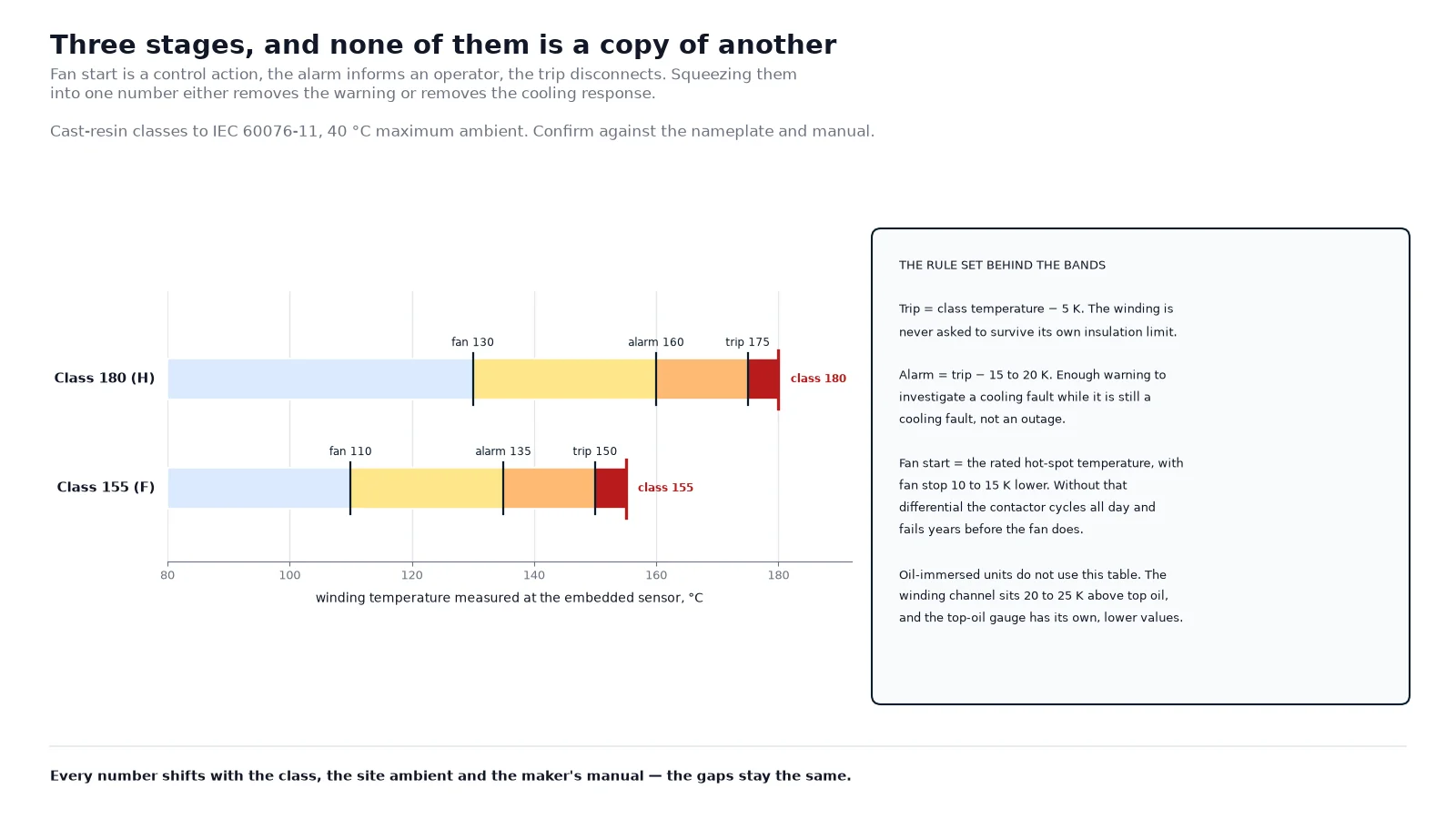
Every number in that table moves with three things: the temperature-rise class of the unit, the maximum ambient at the site, and the transformer manufacturer’s own manual. A unit specified for a 55 °C ambient cannot use a table written for 40 °C. Treat the figures as a starting grid to be checked against the nameplate and the manual, never as a universal default.
The hysteresis is not a detail. With fan start at 110 °C and fan stop at 109 °C, the fan contactor will cycle every few minutes for the whole life of the transformer, and the contactor will fail long before the fan does. A 10 to 15 K differential is what turns a control loop into something that survives a decade.
Why the alarm point matters more than the trip point
The trip protects against a failure that is already happening. The alarm is what prevents it. The quantitative reason is the ageing acceleration factor used in the loading guides:
FAA = exp[ 15000 / 383 − 15000 / (Θh + 273) ]
where Θh is the hot-spot temperature in degrees Celsius and 110 °C is the reference at which FAA equals 1. The function is steep, and its steepness is the whole argument for monitoring.
| Hot-spot temperature |
Ageing rate (FAA) |
Relative insulation life |
| 98 °C |
0.28 |
About 3.5 times |
| 110 °C |
1.00 |
Design life |
| 116 °C |
1.83 |
Just over half |
| 122 °C |
3.29 |
About one third |
| 128 °C |
5.80 |
About one sixth |
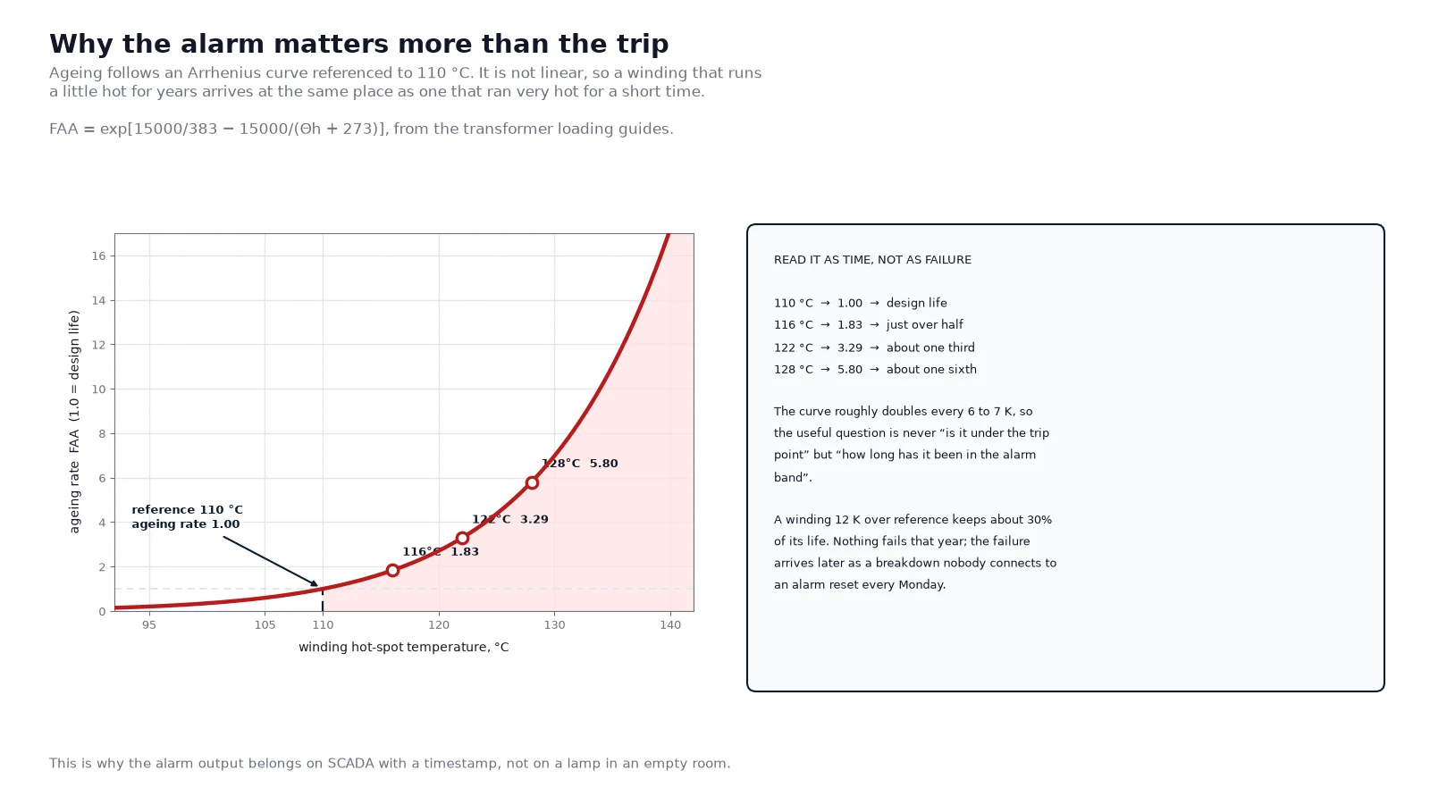
Read the table as a statement about time, not about failure. A winding that sits 12 K above its reference for its whole life does not fail suddenly; it keeps roughly 30% of its design life, quietly, and the failure appears years later as an insulation breakdown that nobody connects to an alarm that was reset every Monday morning. This is why the alarm output should be wired to the SCADA system with a timestamp rather than to a panel lamp in a room nobody visits.
A sanity check against the thermal model
Controllers do fail, and the failure mode is usually a plausible reading rather than a blank display. The way to catch it is to compare what the controller says with what the load says it should be.
The loading guides express the top-oil rise over ambient as a function of load factor K, the loss ratio R (load loss over no-load loss at rated current) and an oil exponent n of about 0.8 for ONAN and 0.9 for ONAF:
ΔΘTO = ΔΘTO,R × [ (K²R + 1) / (R + 1) ]n
For a distribution unit with a 60 K rated top-oil rise and a loss ratio of 6, running at 110% load gives a multiplier of 1.14, so the top-oil rise becomes 68 K. In a 30 °C plant room that is about 98 °C at the gauge. If the controller is showing 62 °C under the same load on the same day, it is not measuring the oil — it is measuring the wall, a pocket that is not immersed, or a channel that has drifted. The same comparison applied to the winding, using a hot-spot gradient of 20 to 25 K above top oil, gives the figure the winding channel should be showing.
The model is not accurate enough to replace a sensor, and it is not meant to be. It is accurate enough to tell you that a sensor has stopped telling the truth, which is the failure mode that matters. One upstream decision feeds the whole calculation: the tap position and the turns ratio fix how much flux the core carries at a given supply voltage, and therefore the no-load loss the thermal design has to live with — the calculation is set out in turns ratio, vector group and tap calculation.
Oil-immersed units: the WTI and its image coil
Most oil-immersed distribution transformers do not have a sensor in the winding at all. They have a winding temperature indicator — a top-oil bulb plus a small heater coil fed from a current transformer on one phase. The heater adds a load-dependent bias to the bulb, so the pointer simulates the hot spot instead of reporting the oil.
The simulation only works if the heater coil is connected and calibrated. A WTI whose heater circuit was left disconnected at commissioning reads top oil, which on a cool day can be 30 K below the hot spot — and the trip contact then never operates at a temperature that matters. The calibration check is simple: at rated current, with the oil at a known temperature, the indicator should read the oil temperature plus the design gradient. Record the reading, and repeat it at the next service.
If a unit has both a top-oil gauge and a WTI, set them separately and label them separately. Applying the winding alarm value to the oil gauge produces an alarm that fires continuously in summer, and the natural response to that is to raise the setting until it never fires at all.
Commissioning sequence that proves the chain
A temperature system is only commissioned when the trip output has actually opened the breaker. The same checks belong in the annual service routine, alongside the fan and duct cleaning that keeps the readings meaningful — the dry-type maintenance routine sets out that side. Work through the list in order and record the as-left settings.
- Identify each sensor against the drawing and label the terminals by phase; a swapped channel is invisible afterwards.
- Measure loop resistance on all three channels at ambient — they should agree within 1 to 2 K of each other.
- Compare the ambient reading with a reference thermometer; a fixed offset means a wiring error, not a calibration error.
- Force each stage in turn — hot-air gun on the probe or a decade resistance box on the input — and confirm the relay operates at its set point.
- Confirm the trip relay actually opens the upstream breaker, not just the controller’s own output contact.
- Run each fan stage manually, check airflow direction, current draw and the status feedback to SCADA.
- Test the differential: the fan must stop only below the drop-out setting, not at the start setting.
- Disconnect one PT100 and confirm the controller reports sensor fault, and does not trip on temperature.
- Check the communication parameters, the register scaling and the max/min memory reset policy, then write the as-left sheet.
Frequently asked questions
Where should the winding temperature sensor be located?
At the top of the winding, on the inner surface facing the core, where the oil flow is poorest and the copper is hottest. On a cast-resin unit that position has to be designed in, because the probe is cast in place. A probe at mid-height reads 5 to 15 K low and will not protect the top of the winding.
Can a fibre-optic sensor be added to an existing transformer?
Not inside the winding. The probe has to be laid between conductor layers before the winding is impregnated or cast. What can be retrofitted is a surface-mounted probe or a tank pocket — both are useful, but neither measures the hot spot, and the settings derived from them should be treated as indicative.
What should the trip temperature be for an F-class dry transformer?
Around 150 °C, which is 5 K below the 155 °C class temperature, with the high-temperature alarm at about 135 °C and fan start near 110 °C. Confirm the class on the nameplate first: a class H unit with class F settings is being protected to a limit 25 K tighter than its insulation needs, and will nuisance-trip.
Why does the controller read close to ambient when the transformer is clearly warm?
Three likely causes, in order of frequency: the probe is in a pocket that is not immersed or not in contact with the winding, the channel is reading open-circuit and has been clamped to a default, or the wiring is a two-wire run whose lead resistance was never compensated. Compare the reading with the thermal model at the actual load before touching the settings.
What is the difference between a WTI and a top-oil thermometer?
A top-oil thermometer measures oil. A winding temperature indicator measures oil plus a heater-coil bias proportional to load, so its pointer approximates the hot spot. The two have different scales and different settings, and applying a winding limit to the oil gauge is a common cause of nuisance alarms.
How often should the maximum-temperature memory be reset?
At every service interval, after the reading has been recorded. The max/min memory is the only evidence of what happened between visits, and resetting it without recording it destroys the record. If the maximum is consistently close to the alarm point, the problem is loading or cooling, not the controller.
What to carry into the inquiry
Five items decide whether a temperature monitoring scheme works: the insulation class and temperature-rise class of the unit, the number and location of embedded sensors, the controller functions required (fan stages, separate sensor-fault output, two-out-of-three voting, Modbus), the maximum ambient at the site, and whether direct hot-spot measurement is needed rather than a thermal model.
Ask for the sensor positions on the outline drawing, not just the sensor count. A unit with six PT100s in the wrong places is less informative than one with three in the right ones, and the difference cannot be corrected after the casting is poured. The dry-type specification guide shows how the temperature-rise class and the sensor arrangement are written into a datasheet, and the cooling class guide explains how the fan stages relate to the AN and AF ratings. For a project where loading will sit near the limit, send the load profile with the inquiry — the engineering team can size the cooling stage and the alarm band against it rather than against a default table.