A cast resin dry type transformer is bought twice. The first time it is a line in a quotation, and the second time it is a unit on a plinth with a nameplate. Everything that goes wrong between those two moments was decided by how precisely the request for quotation was written. When selecting cast resin dry-type transformers, the enquiry usually carries five lines: rating, voltage ratio, vector group, impedance and price. Five inputs are enough to produce a price, and they are not enough to produce a unit that behaves the way the designer assumed.
This is not a criticism of suppliers. A manufacturer will always optimise inside the space the buyer leaves open, because that is what a competitive bid rewards. If the ambient temperature is not stated, the design uses 40 °C. If the temperature rise is not stated, the design runs at the standard limit. If the loss tolerance is not stated, the bid is priced at the top of the band. All of those are compliant, and all of them cost the operator money for twenty-five years.
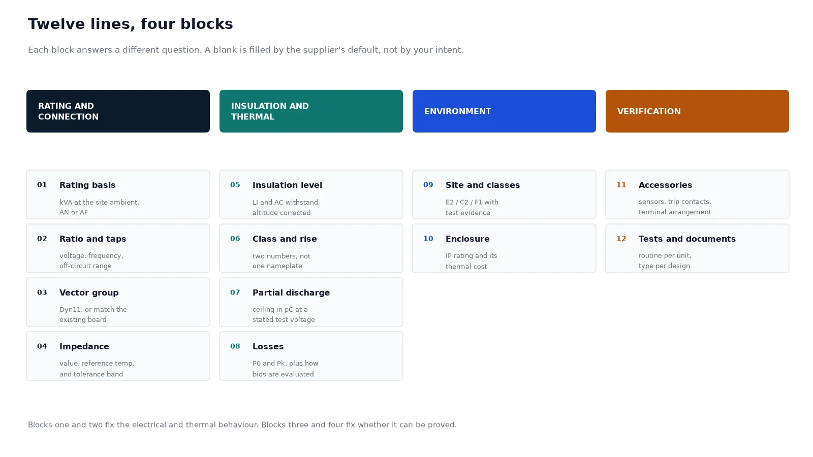
The twelve line items below are the ones that decide whether the delivered transformer matches the one in the single-line diagram. They are grouped in four blocks: rating and connection, insulation and thermal, environment and enclosure, and verification. Each item is written as it should appear in the enquiry, with the consequence of leaving it open.
Why a five-line enquiry produces five different transformers
Consider a 1,000 kVA, 11 kV/433 V unit in a plant room in a hot climate. Supplier A bids a Class F design at 100 K rise, AN cooling, IP21 enclosure. Supplier B bids the same rating at 80 K rise, AN with AF standby, IP23. Both are correct against a five-line enquiry. B is 12% more expensive and will run 20 K cooler, which roughly halves the thermal ageing rate of the insulation. Without the temperature rise and the cooling class in the enquiry, the buyer cannot see that difference, and cannot defend paying for it.
The same asymmetry appears in every one of the twelve items. The purpose of writing them down is not to make the enquiry long. It is to make the bids comparable, so the cheapest compliant offer can be identified as exactly that.
Block one: rating and connection
1. Rating basis: kVA at which ambient, in which cooling mode
Write the continuous rating, the maximum ambient temperature it must hold at, and whether that rating is natural air (AN) or forced air (AF). A cast resin unit rated 1,000 kVA at 40 °C is not a 1,000 kVA unit at 50 °C. Above the 40 °C reference, capacity falls by roughly 0.5% to 0.6% per kelvin, so a 50 °C site loses about 5% to 6% of nameplate before any enclosure is fitted. Ask for the rating at the site ambient, not the catalogue ambient, and ask for the AF rating separately if fans are fitted. On fan failure, the unit must still carry the load that matters — state which load that is.
2. Voltage ratio, tap range and tap type
State the ratio at no load, the rated frequency, the tap range and where the taps sit. A typical distribution specification is 11,000/433 V, 50 Hz, off-circuit tappings of ±2×2.5% on the high voltage winding. Two things go wrong here. First, the frequency is left to the supplier, which matters for units built on 50 Hz laminations and installed on a 60 Hz system, or the reverse. Second, off-circuit versus on-load is not stated; on a cast resin distribution unit the answer is almost always off-circuit, and it should be written so nobody prices an OLTC that will never be used.
3. Vector group
Dyn11 is the default for distribution in most of Europe, the Middle East and Asia, and it is what a supplier will assume if the line is blank. That assumption breaks when the unit has to run in parallel with an existing Yyn0 board, or when a Dd0 unit is needed for a dedicated rectifier or drive load. Write the vector group, and if parallel operation is intended, write the existing units’ vector group and impedance alongside it. Vector group cannot be changed after the coils are cast.
4. Impedance, and the tolerance you will accept
Impedance is the one parameter that changes what happens elsewhere in the system. A higher value limits fault current and softens motor starting dips; a lower value does the reverse, and it also changes the arc-flash calculation. Write the target percentage at the reference temperature and on which base, then write the tolerance explicitly. IEC 60076-1 permits ±7.5% of the declared value when impedance is 10% or above, and ±10% below 10%. On a 6% unit that is a band from 5.4% to 6.6% — two transformers that both pass and behave differently. If the unit will run in parallel, tighten the band to ±5% in the purchase order, and require the measured value on the routine test report to be used in the protection study.
Block two: insulation and thermal limits
5. Insulation level, including the altitude correction
State the highest system voltage and both withstand values. For a 12 kV system the standard dry-type levels are a 75 kV lightning impulse and a 28 kV power-frequency withstand; 24 kV takes 125 kV and 50 kV; 40.5 kV takes 200 kV and 85 kV. Then state the site altitude. IEC 60076-11 requires the separate-source AC withstand to rise by 1% for every 100 m above 1,000 m, up to 3,000 m, when the unit is tested at normal altitude. A project at 1,800 m therefore needs 8% more AC withstand than the catalogue figure, and it will not get it unless the enquiry says so.
6. Insulation class and temperature rise: two numbers, not one
These are routinely conflated, and the confusion is expensive. The insulation class is a property of the materials — Class F is 155 °C, Class H is 180 °C. The temperature rise is a design decision inside that class. IEC 60076-11 caps the average winding rise at 100 K for a Class F system and 125 K for Class H, measured against a 40 °C maximum ambient. A supplier can therefore offer a genuine Class F transformer that runs at the full 100 K, or a Class F transformer designed at 80 K with more copper and a much longer life. Both nameplates say Class F. Specify the rise you want, and specify the hot-spot allowance separately, because the average rise hides the difference between an evenly cooled winding and one with a hot band. How the two values are printed, and what a realistic pair looks like for a given rating, is visible in the datasheet of a standard insulation series unit.
7. Partial discharge ceiling
Partial discharge is the only routine test that looks inside the casting. The usual acceptance ceiling is 10 pC at 1.1 times the phase-to-earth voltage, and premium specifications ask for 5 pC, quoted per phase with the test voltage printed next to the result. A report that says “PD test: passed” without a number and a test voltage is not evidence. This is worth arguing about on a cast resin unit because a void in the resin cannot be inspected, rewound or repaired later — the failure mode is a slow erosion from the inside that ends in a flashover, often in year eight rather than year one.
8. Losses and how they will be evaluated
Ask for no-load loss, load loss and total loss as guaranteed values at a stated reference temperature, and ask for the tolerance basis. Under IEC 60076-1 the measured total may exceed the guarantee by 10%, and each component by 15%, provided the total limit is not exceeded. That means a guaranteed 9 kW no-load figure can legitimately test at 10.35 kW and consume roughly 11,800 kWh more per year, for the life of the unit, on a transformer that passed every test.
The commercial fix is to evaluate losses instead of comparing prices. Use total owning cost: purchase price plus the capitalised value of no-load loss plus the capitalised value of load loss at the expected average loading, with the capitalisation factors agreed before bids are opened. Where efficiency legislation applies — EU Regulation 548/2014 Tier 2 for units from 25 kVA, or 10 CFR 431 in the United States, which evaluates dry-type units at 35% load — require compliance to be demonstrated from the routine test results rather than from a calculation.
| Parameter |
What to write |
What happens if it is left open |
| Rating basis |
1,000 kVA continuous at 45 °C site ambient, AN, AF standby |
Unit is rated at 40 °C and loses 5% of capacity on site |
| Voltage and taps |
11,000/433 V, 50 Hz, off-circuit ±2×2.5% on HV |
Frequency assumed, or an unused OLTC is priced in |
| Vector group |
Dyn11, matching existing board for parallel duty |
Default assumed; parallel operation impossible |
| Impedance |
6.0% at 120 °C, tolerance ±5% because of parallel duty |
±10% band shifts fault level and load sharing |
| Insulation level |
Um 12 kV, LI 75 kV, AC 28 kV, site altitude 1,800 m |
No altitude correction; 8% short on withstand |
| Thermal design |
Class F insulation, 80 K average rise, 20 K hot-spot allowance |
Unit runs at 100 K and ages at roughly twice the rate |
| Partial discharge |
≤5 pC at 1.1 Um/√3, value reported per phase |
10 pC ceiling accepted, no measured numbers on file |
| Losses |
P0 and Pk guaranteed at 120 °C, evaluated at agreed factors |
Bid won at top of the loss tolerance band |
| Environment |
IEC 60076-11 C2, E2, F1 with test reports |
Class letters quoted with no evidence behind them |
| Enclosure |
IP23, louvred, filtered, 300 mm clear to walls |
IP54 specified for looks, capacity silently derated |
| Accessories |
2×PT100 per LV winding, controller with alarm and trip |
One sensor per phase, no trip contact, no spare |
| Verification |
Routine report per unit, type reports by design, FAT witnessed |
Documents arrive after the container does |
Block three: environment and enclosure
9. Site conditions and the IEC 60076-11 class letters
A cast resin transformer carries three independent classifications, and they are frequently quoted as one decorative string on a datasheet. Climatic class C1 means operation to −5 °C with transport to −25 °C; C2 means operation, transport and storage to −25 °C, proven by a cold test. Environmental class E1 allows occasional condensation and limited pollution; E2 allows frequent condensation or heavy pollution, proven by a humidity penetration test. Fire class F1 requires restricted flammability with limited smoke and toxic emission, proven by a fire test.
The useful instruction is to describe the site, then ask the bidder to declare which classes the offered design holds and to attach the report identifier, the laboratory and the standard edition. A coastal plant with frequent condensation needs E2. A cold-store project needs C2. A unit inside a hospital basement needs F1. A statement that the design is “tested to IEC” answers none of those questions.
10. Enclosure, ingress protection and the cooling path
Write the IP rating and the reason for it, because each step up the scale closes part of the airflow path the coils depend on. IP20 keeps fingers out and leaves natural convection intact. IP23 adds a rainproof louvre and costs some free area. IP54 closes the box almost completely, and the honest options are then a larger transformer, forced ventilation, or a documented derating. In a hot climate, an IP54 enclosure in direct sun can turn a well-designed unit into an oven within one summer.
Also write the practical items that decide whether the enclosure works: minimum clearance to walls and ceiling so the air can rise, filter type and how it is cleaned, whether the fan supply and control are inside the enclosure, and whether the HV and LV cable entries are top or bottom. Enclosure decisions are cheap at enquiry stage and expensive afterwards, because the coil-to-wall distance is fixed by the outline drawing.
Block four: verification and documents
11. Accessories and interfaces
List them, because accessories are where a compliant bid quietly becomes an incomplete one. At minimum: two PT100 sensors per low voltage winding plus a spare, a winding temperature controller with alarm and trip contacts rated for the upstream breaker, fan control with auto and manual modes, two earthing terminals, lifting lugs, jacking pads, HV and LV terminal arrangements (cable box or busbar, and the direction), a space heater for condensation control, terminal markings to IEC 60076-1, and the paint colour by RAL number. Where the unit feeds a critical load, add the interface to the building management system in the same list.
12. Tests, witness points and the document pack
Split the requirement into routine, type and special, then name the witness points. Routine tests on every unit include winding resistance, ratio and vector group, impedance and load loss, no-load loss and current, applied voltage, induced voltage with partial discharge measurement, and insulation resistance. Temperature rise, lightning impulse and short-circuit withstand are type or special tests, which means the evidence exists once per design rather than once per unit — so ask for the report that covers the design, the rating range and the year, not a generic certificate.
Finally, write the document pack into the order: outline drawing for approval before manufacture starts, certified routine test report per serial number, calibration certificates for the instruments used, IEC 60076-11 class test reports, operation and maintenance manual, and a nameplate photograph taken before crating. A buyer who receives the test report after the container has arrived has lost the only cheap moment to resolve a discrepancy.
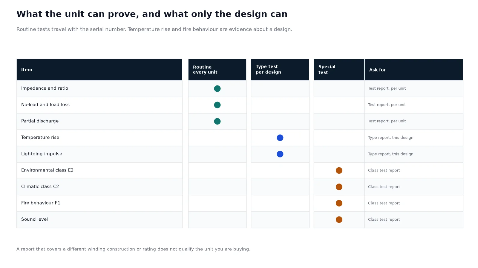
Which lines cannot be verified on the unit you receive
The difference between a routine test and a type test is the difference between “this unit is right” and “this design is right”. Most of the twelve items fall in the first category and are cheap to check. The expensive ones — temperature rise, impulse withstand, fire behaviour, environmental class — can only be verified by a report on the design, which is why they belong in the enquiry rather than in the acceptance conversation.
| Item |
Routine, every unit |
Type or special, per design |
| Impedance |
Measured and reported |
— |
| Losses |
P0 and Pk measured and corrected |
— |
| Partial discharge |
Measured per phase at stated voltage |
— |
| Temperature rise |
— |
Heat run to the declared rise and ambient |
| Insulation level |
Applied and induced voltage |
Lightning impulse, altitude-corrected values |
| Environmental and climatic class |
— |
E2 humidity penetration, C2 cold test |
| Fire behaviour |
— |
F1 fire test report |
| Sound level |
— |
LWA measurement per IEC 60076-10 |
Three traps that survive a well-written enquiry
The compliant unit at the top of every tolerance band. Impedance at +10%, losses at +15% on each component, no-load current at +30%. Every one of those is permitted, and together they describe a transformer that is measurably worse than the one the bid was compared against. If losses are evaluated, this trap closes on its own.
Temperature rise quoted without its ambient. “Class F, 100 K rise” is meaningless unless it says at 40 °C. At a 50 °C site the same winding sees a 10 K higher hot spot, and the ageing rate roughly doubles for every 7 to 10 K. The enquiry should state the ambient and ask for the rise at that ambient, or for the derating that keeps the hot spot inside the class.
A type test report for a different design. Ask for the report to identify the winding construction, the rating range and the insulation system it covers. A report for a 1,600 kVA unit at a different voltage class does not qualify a 630 kVA unit, and a report for a VPI winding does not qualify a cast resin one. Where the construction choice is still open, the comparison between cast resin, VPI and open-wound designs belongs upstream of the enquiry — the specification then only records the decision.
What to do with the twelve lines
Put them in the enquiry as a numbered schedule, and require bidders to answer line by line rather than in a brochure. The schedule then becomes the comparison sheet, the purchase order annex and the acceptance checklist, which is the point: one document that survives from enquiry to energisation.
Two references make the exercise faster. A specification sheet shows how the values are normally presented and which ones the standards fix, and the technical data for a given rating shows what a realistic set of numbers looks like before the enquiry is issued. A standard 10 kV cast resin unit also shows, in one picture, the coil, fan and terminal arrangement that items 10 and 11 are describing. If the unit is going into a building where the fire case decides the technology, the wider trade-off between cast resin, VPI and open-wound construction is worth settling first, because it changes items 6, 7 and 9 together.
FAQ
What should a cast resin dry type transformer specification include?
At minimum: rating at the site ambient with the cooling mode, voltage ratio, frequency, tap range and type, vector group, impedance with tolerance, insulation level with altitude correction, insulation class and temperature rise as separate values, partial discharge ceiling, guaranteed losses with an evaluation method, IEC 60076-11 classes, IP rating, accessories, and the test and document requirements. Twelve lines, one page.
Is Class F insulation the same as a 100 K temperature rise?
No. Class F describes the material system, rated to 155 °C. The 100 K figure is the maximum average winding rise IEC 60076-11 permits for that class at 40 °C ambient. A Class F transformer designed at 80 K is common and is a better purchase for continuous duty, because the lower rise roughly halves the thermal ageing rate.
What partial discharge level should I specify?
Specify 10 pC as the absolute ceiling and 5 pC if the unit is critical, both measured at 1.1 times the phase-to-earth voltage, with the result reported per phase and the test voltage stated. Require the measured value, not a pass mark; the value is the early indicator of a casting problem.
How much impedance tolerance is acceptable?
IEC 60076-1 allows ±7.5% above 10% impedance and ±10% below it. For a single unit that is tolerable. For units that will run in parallel, tighten the band to ±5% in the order, because two units at opposite ends of a ±10% band differ by up to 20% and will not share load evenly.
Should I specify AN or AF cooling?
Specify AN as the continuous rating and AF as a defined standby capacity, then state the load that must survive fan failure. Fans add roughly a quarter to a third of the AN rating, but they also add a maintenance item and a single point of failure that a passive unit does not have.
Which documents should arrive with the transformer?
An approved outline drawing, a certified routine test report matched to the serial number, instrument calibration certificates, measured partial discharge values, the IEC 60076-11 class test reports for the design, the operation and maintenance manual, and a nameplate photograph taken before packing. The temperature rise and impulse reports are design evidence, so confirm they cover the rating and construction actually purchased.