Most buyers see a dry type transformer twice: as a PDF datasheet and as a box on a pallet. The twenty steps in between are where the loss figures are created, where the partial discharge performance is decided, and where the delivery date is either held or lost. Understanding those steps is the difference between auditing a factory and walking through it.
This is a step-by-step account of how a dry type power transformer is actually built, in the order the shop floor builds it, with the checkpoints that matter at each stage. It is written for the person who has to sign an inspection plan, visit a supplier, or explain to a project team why a change order on the winding specification moved the delivery date by three weeks.
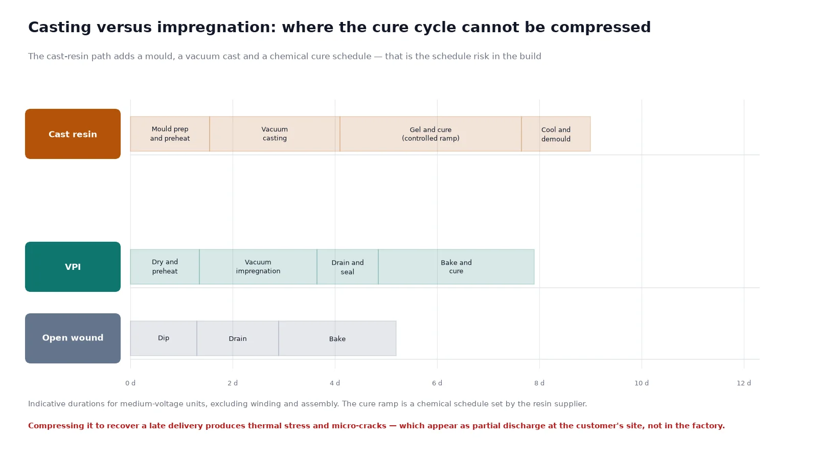
One caveat before we start: the specific sequence varies by manufacturer and by construction type. A VPI unit skips the casting steps entirely and substitutes an impregnation and bake cycle. An open-wound unit skips both. The logic below is the cast-resin path, which is the most common construction for indoor medium-voltage distribution, and the notes flag where the other constructions diverge.
Quick answer: the five phases
The twenty steps group into five phases. Roughly 40 percent of the calendar time sits in design and material procurement, 25 percent in core and coil work, 20 percent in casting and curing, and the remainder in assembly, test and packing.
| Phase |
Steps |
What it fixes |
Where projects slip |
| 1. Engineering and material |
1 to 4 |
Loss figures, impedance, temperature rise, BOM |
Specification not frozen; core or conductor lead time |
| 2. Core and coil |
5 to 10 |
No-load loss, load loss, short-circuit strength |
Winding machine capacity; tap section rework |
| 3. Casting and curing |
11 to 14 |
Dielectric strength, partial discharge, moisture immunity |
Mould preparation; cure cycle cannot be compressed |
| 4. Assembly |
15 to 17 |
Mechanical integrity, clearances, enclosure protection |
Enclosure fabrication; accessory availability |
| 5. Test and dispatch |
18 to 20 |
Proof of performance; the evidence package |
Retest after a failed PD or loss measurement |
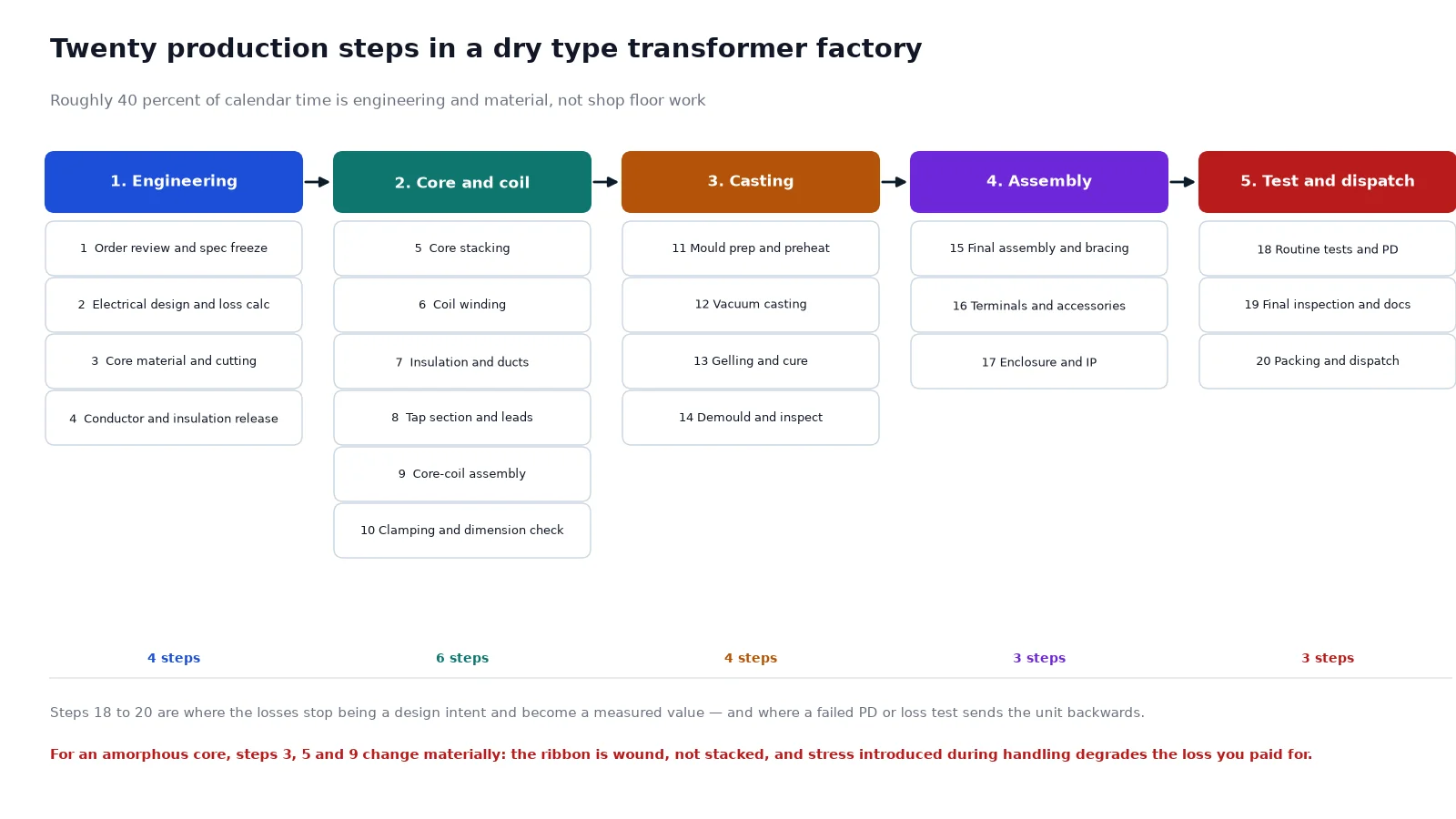
Phase 1: engineering and material (steps 1 to 4)
Step 1: order review and specification freeze
Before any steel is cut, the order has to be converted into a design input that cannot move. Voltage ratio, vector group, rated power, impedance, temperature rise, insulation level, tap arrangement, enclosure protection, ambient basis and the applicable standard are fixed here. Every one of these that is left open becomes a change order later, and a change order after the mould is made is the most expensive kind.
The practical checkpoint is a signed design input sheet. If a supplier starts cutting core steel against a verbal understanding, the delivery date is already at risk.
Step 2: electrical design and loss calculation
The designer selects core flux density, conductor current density, number of turns, winding arrangement and duct geometry, and from those computes the guaranteed no-load and load losses, the impedance, and the winding hot-spot temperature rise. This is the step where the declared efficiency is created. Everything afterwards either achieves the number or fails to.
Ask to see the calculation, not just the result. A loss guarantee that cannot be traced to a design calculation is a number with no owner.
Step 3: core material selection and cutting
Grain-oriented electrical steel arrives as coils, typically 0.23 to 0.30 mm thick, and is cut to length for step-lap stacking. The cut quality matters: burrs increase interlamination loss and can create local hot spots. For an amorphous unit this step is different in kind, because the ribbon is wound rather than stacked, and the handling discipline around stress is far tighter.
This is also where an efficiency-level decision becomes physical. The same rating built to two different efficiency levels uses different core mass and sometimes different grade, which is why two quotes with the same kVA can differ by a meaningful percentage.
Step 4: conductor and insulation material release
Copper or aluminium conductor, insulation paper or enamel, cast-resin system components, and the accessory list are released to the shop. Conductor grade and insulation thickness are not interchangeable, and substituting them without recalculating losses and temperature rise quietly changes the product.
Phase 2: core and coil (steps 5 to 10)
Step 5: core stacking
Laminations are stacked in step-lap arrangement to reduce the air-gap loss at the joints, then clamped. The clamping pressure has to be enough to keep the stack tight and not so much that it degrades the magnetic properties. A poorly stacked core shows up later as excess no-load loss, and it is one of the few defects you can detect before the coils go on, which is why core inspection is a natural hold point.
Step 6: coil winding
Windings are wound on a mandrel or directly on the insulation cylinder, depending on the construction. Cast-resin medium-voltage units commonly use layer or foil windings for the low-voltage side and layer windings with cast insulation for the high-voltage side. Turns count, conductor dimensions, insulation thickness and the position of the tap section are all set here.
Winding tension and the alignment of the conductor are the two variables that most affect short-circuit strength. A winding that looks correct but is loosely wound will move under fault current, and no routine test will catch it.
Step 7: insulation and duct assembly
Insulation cylinders, spacers and cooling ducts are placed. Duct geometry is a cooling decision and a dielectric decision at the same time: it sets the temperature rise and it sets the creepage path. Changing duct arrangement to fit an enclosure is not a neutral act.
Step 8: tap section and lead forming
Off-circuit tappings are brought out and the leads are formed and dressed. Lead dressing affects clearance and also affects partial discharge if a lead is routed too close to a sharp edge. This is a step where a small shop-floor error produces a unit that passes ratio tests and fails on PD.
Step 9: core-coil assembly
The wound coils are assembled onto the core limbs, and the core is closed. For a wound amorphous core, the core is opened, the coils inserted and the core re-closed, which is the single most delicate operation in the whole build. Any damage here shows up as a loss deviation, not as an obvious defect.
Step 10: clamping and dimensional check
The assembly is clamped, the phase-to-phase and phase-to-earth clearances are measured, and the overall dimensions are checked against the general arrangement drawing. This is also the moment to confirm the unit will fit the enclosure and the cable boxes will align with the actual incoming cables.
Phase 3: casting and curing (steps 11 to 14)
Step 11: mould preparation and preheating
The winding is placed in a mould and the assembly is preheated. Mould sealing and preheat uniformity are critical: a cold spot or a leak produces voids, and voids produce partial discharge. This step consumes a full shift and cannot be accelerated.
Step 12: vacuum casting
The mould is evacuated and filled with the filled epoxy resin system under vacuum, so that air is drawn out of the winding before the resin sets. Vacuum quality and resin temperature are recorded process parameters. This is the step that determines whether the finished winding is a sealed solid body or a body with hidden cavities.
Step 13: gelling and cure
The filled mould goes through a controlled temperature profile: gel, then cure, then a controlled cool-down. The cure cycle is a chemical schedule, not a manufacturing preference. Attempting to shorten it to recover a late delivery produces thermal stress and micro-cracks that show up as PD at the customer’s site rather than in the factory.
Step 14: demoulding and inspection
The casting is demoulded and inspected for surface defects, resin completeness and dimensional conformity. Small surface voids can be repaired; voids near the conductor cannot. This inspection is the last point before the unit becomes expensive to scrap.
Phase 4: assembly (steps 15 to 17)
Step 15: final core-coil assembly and bracing
The cast coils are assembled with the core, braced and connected. Bracing design is the short-circuit strength design, and it is largely invisible in the finished product. On site, the only evidence of it is the short-circuit type test report.
Step 16: terminal, tap link and accessory installation
Terminals, tap links, temperature sensors, cooling fans if fitted, and the earthing terminals are installed. This is where the difference between a good and a great specification shows up in practice: whether the cable box orientation matches the site, whether the sensor wiring is accessible, whether the fan control is serviceable.
Step 17: enclosure and protection assembly
The unit is fitted into its enclosure, and the IP protection is realised through gaskets, gland plates and door seals. An IP rating is a system property, not a label: a correctly rated enclosure with a badly sealed cable entry is not IP-rated in service.
Phase 5: test and dispatch (steps 18 to 20)
Step 18: routine tests
Winding resistance, ratio and polarity or vector group, no-load loss and current, load loss and impedance, applied voltage and induced voltage withstand, and partial discharge measurement. Each of these produces a recorded value, and the loss values are the ones the buyer will compare against the guarantee.
Before the loss tests, check instrument calibration. A loss measurement taken on an uncalibrated analyser is not evidence, and this is the single most common weakness in a factory test package.
Step 19: final inspection and documentation
The unit is inspected against the general arrangement, the nameplate data is verified, and the document package is assembled: routine test certificate, loss records, PD trace, material certificates, and the drawing set. If the project has an inspection and test plan, this is where the hold points have to be evidenced rather than merely claimed.
The broader question of what a complete inspection package should contain, and which hold points actually stop work, is covered in our guide to power transformer quality inspection, which applies to dry-type units with the oil-related items removed.
Step 20: packing and dispatch
The unit is braced, wrapped, and packed for its transport mode. Dry-type units are lighter than oil-filled units of the same rating but more sensitive to moisture and to mechanical shock on the cast body. Packing therefore has to address both, and the packing method should match the shipping duration rather than the shipping cost.
Factory audit: ten checkpoints that actually reveal something
A factory tour shows you machines. An audit should show you control. These ten items separate the two, and the wider context for how a supplier is qualified at all sits in our guide to choosing a transformer manufacturer.
| Checkpoint |
What to ask for |
What a weak answer looks like |
| Core material traceability |
Mill certificates matched to the specific order |
“We use grade X” with no lot linkage |
| Winding tension control |
Machine settings logged per unit |
Operator experience as the only control |
| Vacuum casting records |
Vacuum level and resin temperature per batch |
No records retained after the shift |
| Cure profile records |
Time and temperature chart per casting |
Cure time quoted as a fixed number of hours |
| PD test capability |
Calibrated PD set, background noise figure, recorded traces |
PD stated as “passed” with no trace |
| Loss measurement calibration |
Calibration certificates in date for the analyser and CTs |
Certificate expired or not produced |
| Short-circuit type test |
Report from a recognised laboratory at a comparable rating |
Type test at a much smaller rating, claimed as equivalent |
| Rework and NCR log |
Open and closed non-conformities with disposition |
No NCR log, which usually means no NCR reporting |
| Enclosure sealing |
Gasket specification and gland plate design |
IP claimed by enclosure supplier only |
| Document control |
Revision-controlled drawings issued to the shop |
Shop working from undated prints |
Why the twenty steps explain the price and the lead time
Three of the steps dominate the commercial picture. Design and loss calculation determines whether the unit meets a given efficiency level with a given core mass, which is most of the material cost. Winding and casting determine the labour content and the scrap risk, which is why a factory with poor casting yield quotes a higher price. Testing determines the schedule risk, because a unit that fails PD or loss has to be investigated, and in the worst case rebuilt.
When one supplier quotes twenty percent less than another for the same declared rating, the difference is almost never in the core. It is in one of these: a lower efficiency level than the other unit, a thinner enclosure, a cheaper cast-resin system, fewer tests, or a shorter cure cycle. Asking which step was economised is a more productive conversation than arguing about the headline price.
Two related references fill in the rest. Our comparison of cast resin, VPI and open-wound constructions shows which of the above steps disappear in each construction, and the dry type transformer technical data sheet lists the data you should require against each step before acceptance. If the unit is specified with an amorphous core, the core handling steps change materially and the SCBH amorphous core dry type transformer guide explains why. The reference build for a standard 10 kV cast-resin unit is the epoxy resin 10 kV dry type transformer, and the plant and quality system behind the twenty steps are described on our about us page.
FAQ
How long does it take to manufacture a dry type transformer?
For a standard 10 kV cast-resin unit in the 630 to 2500 kVA range, shop time after material release is typically two to four weeks, with the casting and curing phase taking several days per unit and often running in parallel across batches. The calendar time from order to dispatch is usually dominated by engineering approval and material lead time rather than by the shop floor, which is why a specification change has more schedule impact than a production problem.
Can the cure cycle be shortened to meet a delivery date?
No, not safely. The cure profile is a chemical schedule set by the resin system supplier. Compressing it produces incomplete cure and thermal stress, which typically appears as partial discharge or surface cracking after the unit is in service rather than in the factory test. A supplier willing to shorten the cure cycle to win a schedule argument is telling you something about how they handle other pressures.
Which steps should a buyer witness?
Core inspection, winding completion, casting, and routine tests cover the four points where a defect is either created or proven. If travel is limited, witness the routine tests and review the records for the other three. A PD trace and a calibrated loss measurement tell you more about the whole process than a day of walking the shop floor.
Does a factory visit actually improve quality?
It improves the probability that the documentation matches reality. The audit value is in the records: cast logs, calibration certificates, type test reports and the NCR log. A tour that shows clean floors and busy machines without those records proves very little.
What is the difference between a routine test and a type test?
Routine tests are performed on every unit and include ratio, resistance, losses, impedance, voltage withstand and partial discharge. Type tests are performed once on a representative design and include temperature rise, impulse, and short-circuit withstand. A type test report covers a design family, not your specific unit, so check that the tested rating and construction actually match what you are buying.
Why do two quotes at the same kVA differ so much?
Almost always because one of the twenty steps was economised. The usual candidates are the efficiency level, the core grade and mass, the cast-resin system, the enclosure protection, the test scope, and the accessory package. Ask for a line-by-line comparison against your specification rather than comparing headline prices, because a lower price with a lower efficiency level is not a discount.
If you are preparing a factory audit or an inspection and test plan, send the rating, the efficiency level and the standard you are buying to, and we will confirm which of these twenty steps your plan should hold and what evidence to require at each one.