A unit substation transformer is rarely bought as a loose transformer. It is bought as one coordinated block: medium-voltage switching at the front, a step-down transformer in the middle, low-voltage distribution at the back, all bolted together on a common base and tested as one assembly. That single decision — buy a coordinated block instead of three packages — changes who owns the interfaces, what the type test certificate covers, and how many days the site crew spends waiting for concrete.
This guide walks through the configurations that actually get specified, the standard boundaries between a unit substation and a prefabricated compact substation, the impedance decision that fixes your low-voltage fault level for the next thirty years, and the derating trap that appears the moment a transformer goes inside an enclosure. It closes with a specification checklist you can paste into an RFQ. If you are still choosing the transmission-to-distribution layer instead, our switchgear and substation solutions page shows how the MV and LV sections are normally paired in these projects.
What a Unit Substation Is, and What It Is Not
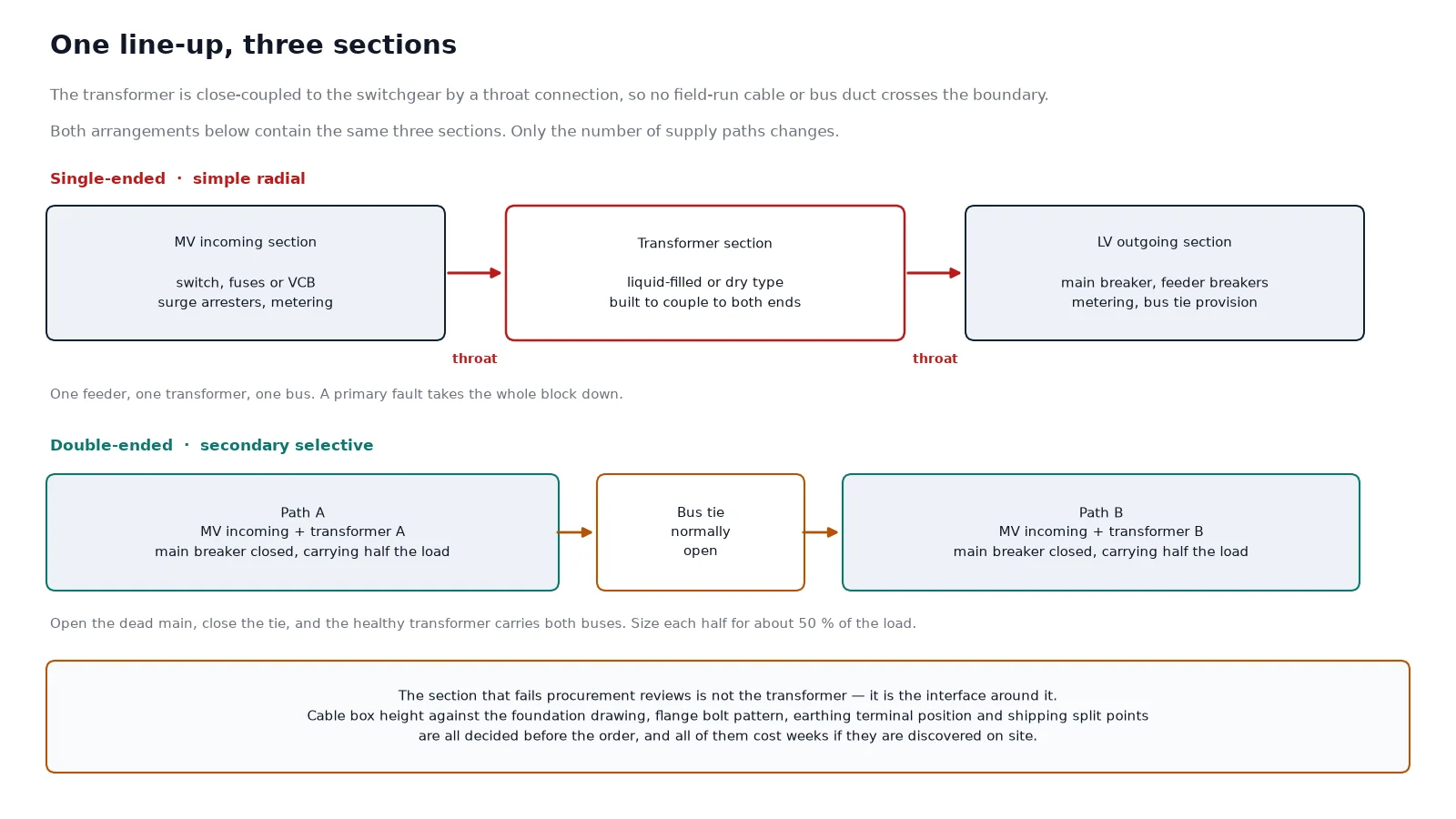
In North American practice, a unit substation is an assembly of metal-enclosed, unitised equipment made of three functional sections:
- Incoming section — medium-voltage cable terminations, load-break switches, fuses, or vacuum circuit breakers, plus surge arresters and metering.
- Transformer section — a liquid-filled or dry-type step-down transformer, mechanically built to couple directly to the adjacent enclosures.
- Outgoing section — low-voltage switchgear or a switchboard with a main breaker and feeder breakers.
IEEE C37.121 is the document that defines this equipment: three-phase step-down unit substations rated 112.5 kVA and above, with primary voltages from 601 V through 52 kV. A transition section can be added where the sections do not align physically.
The word “unit” is doing real work. Three separate packages placed side by side on a slab are not a unit substation, even when the drawings look identical. What makes it a unit is the coordination:
- Mechanical — a close-coupled throat or flange joins the transformer terminals to the switchgear busbars, so no field-run cable or bus duct crosses that gap.
- Electrical — one continuous ground bus, and short-circuit bracing matched across the whole line-up rather than per section.
- Documentary — one set of routine test records, one lifting plan, one warranty owner.
That last point is the one buyers underestimate. When a project runs late, the delay is almost never a failed component. It is two suppliers pointing at each other over a cable box height, a flange bolt pattern, or a delivery date.
Unit, Package, Compact, Pad-Mounted: the Names Are Not Interchangeable
Supplier catalogues mix these four terms freely. For specification purposes they are different products governed by different standards, and the difference matters most when something goes wrong.
| Type |
Defining feature |
Governing standard |
Typical range |
| Unit substation |
Engineered sections — incoming, transformer, outgoing — close-coupled into one line-up |
IEEE C37.121 |
112.5 kVA and up, primary 601 V to 52 kV |
| Prefabricated / compact substation |
Enclosed HV/LV assembly, walk-in or non-walk-in, cable-connected on site |
IEC 62271-202 |
Above 1 kV up to 52 kV |
| Package substation |
Loose commercial term, usually meaning a factory-assembled enclosure |
Whichever the vendor declares |
Vendor dependent |
| Pad-mounted transformer |
One transformer in a tamper-resistant enclosure, no integral LV switchgear line-up |
IEEE C57.12.34 and related product standards |
Distribution kVA classes |
A pad-mounted unit is a transformer you can lock. A unit substation is a distribution block you can operate. If your scope includes feeder breakers, metering, and automatic transfer, you are specifying the second one. The differences in enclosure, access, and clearances are covered in our comparison of pole-mounted and pad-mounted transformers.
Four Bus Arrangements, Four Different Budgets
The single line diagram decides cost and reliability more than any component choice. The four arrangements below are listed in increasing order of reliability and, predictably, increasing cost.
| Arrangement |
Structure |
Behaviour on a primary failure |
Fits |
| Simple radial |
One feeder, one transformer, one LV bus |
Total loss until the feeder is restored |
Small plants, non-critical loads |
| Primary selective |
One transformer, two incoming feeders with selector switches |
Manual or automatic transfer at MV, LV bus stays energised after a short outage |
Facilities with two utility feeds |
| Loop feed primary |
Both primary switches normally closed on a loop |
Either feeder can carry the block; no switching needed for a single cable fault |
Campus and utility loop networks |
| Secondary selective (double-ended) |
Two transformers, two LV mains, normally open bus tie |
Open the dead main, close the tie, the healthy transformer carries the whole load |
Data centres, hospitals, continuous process |
A double-ended line-up is two single-ended blocks joined by a tie breaker. Design each half for roughly half the total load, then confirm the surviving transformer can carry 100% for the duration of a repair. That calculation — not the marketing brochure — is what decides the kVA rating. Forced cooling can close a small shortfall, but only if the fans and their control circuit are on the critical supply.
Primary vs Secondary Unit Substations
The naming refers to what comes out of the last section, not to what goes in.
| Parameter |
Secondary unit substation (power centre) |
Primary unit substation |
| Incoming voltage |
2.4 kV to 34.5 kV |
Typically 34.5 kV to 138 kV |
| Transformer rating |
112.5 kVA to 2,500 kVA (self-cooled base rating) |
Multi-MVA, often several units |
| Output |
208, 240, 480, or 600 V |
2.4 kV to 34.5 kV |
| Outgoing section |
Low-voltage switchgear with feeder breakers |
Medium-voltage metal-clad switchgear |
| Typical use |
Plant load centre, close to the machines it feeds |
Campus or utility distribution node |
Secondary unit substations exist to shorten low-voltage runs. Pushing 480 V a few hundred metres costs copper and voltage; pushing 11 kV the same distance costs very little. Placing the transformation close to the load is the whole economic argument, and it is why the footprint question and the electrical question are the same question.
Choosing the Transformer Inside the Enclosure
Liquid-filled or dry-type is usually decided by location before it is decided by price.
- Liquid-filled — better overload tolerance, lower cost per kVA, quieter, and the default for outdoor blocks. It brings oil containment, fire separation, and bunding requirements.
- Dry-type, cast resin — no fluid, reduced fire load, suitable indoors and in cable rooms. Heavier per kVA at larger ratings and more sensitive to enclosure heat.
- Dry-type, VPI or open-wound — a lower-cost answer for smaller ratings where the environment is clean and controlled.
Whichever you choose, four numbers on the datasheet decide whether the block works: rated power at the specified cooling class, temperature rise, impedance, and tap range. Off-circuit taps of plus or minus 2 x 2.5% are common; on-load tap changers belong on distribution networks with wide voltage swings, not on every unit by default. Our guide to dry-type transformer specification covers how those fields interact, and the oil-immersed power transformer range shows the ratings and cooling classes normally available for outdoor blocks.
For a 35 kV primary block, the transformer section is often the long-lead item. A representative starting point is a 35 kV oil-immersed distribution transformer, but confirm the impedance and tap range against the switchgear ratings before the order is placed, not after.
Impedance and Let-Through Current: the Decision Nobody Revisits
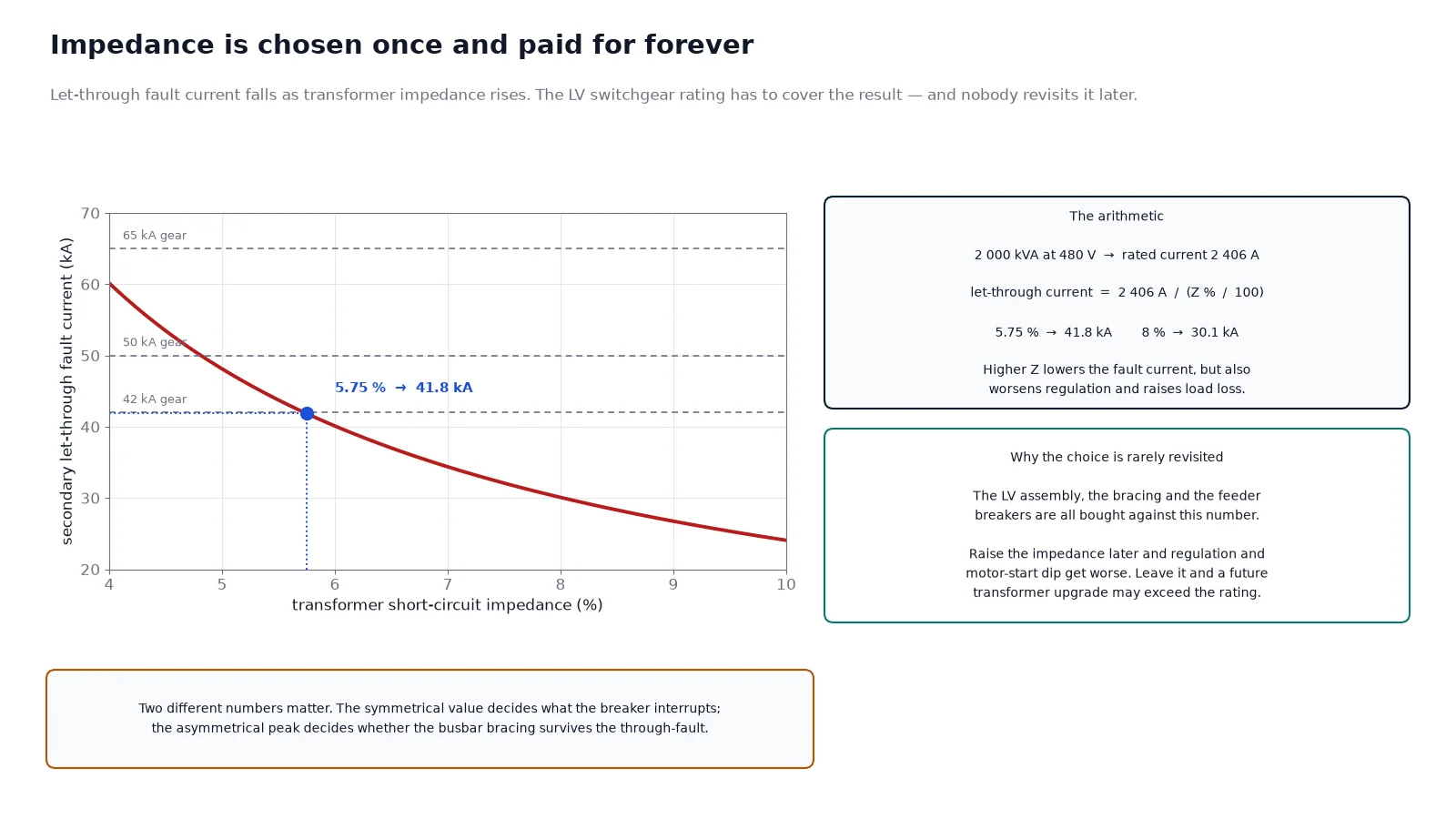
Transformer impedance sets the fault current that the low-voltage switchgear has to interrupt. It is chosen once, usually early, and then treated as untouchable for the life of the building.
The arithmetic is simple. Take a 2,000 kVA transformer with a 480 V secondary and 5.75% impedance:
- Rated secondary current = 2,000,000 / (1.732 x 480) = about 2,406 A.
- Let-through fault current = 2,406 / 0.0575 = about 41,800 A.
That number drives everything downstream. Specify 65 kA breakers and the panel is comfortable. Specify 42 kA breakers and there is no margin for a utility upgrade or an additional transformer later. Raise the impedance and the fault current falls, but voltage regulation gets worse, losses rise, and motor starting dips get deeper. There is no free option; there is only a documented trade-off. The load-side arithmetic is set out in our guide to transformer kVA sizing.
Fault current has two faces. The symmetrical value decides what the breaker can interrupt. The asymmetrical peak decides whether the busbar bracing survives. The low-voltage assembly must be braced for that peak under IEEE C37.20.1 or IEC 61439-2, and the bracing must be continuous across the transformer throat, because that is where the mechanical stress concentrates.
The Enclosure Changes the Rating
This is the most common technical error in package substation procurement: a transformer rated in free air is not rated the same way inside a steel box with louvres.
IEC 62271-202 governs prefabricated substations for rated voltages above 1 kV up to 52 kV, in walk-in and non-walk-in versions. It exists partly because enclosures change thermal behaviour. The standard’s temperature-rise test method for a transformer inside an enclosure, and the load factor curves for liquid-filled units, both acknowledge the same physical fact: heat that cannot leave raises the winding temperature at the same kVA. Two identical transformers — one in free air, one inside an assembly — do not share a rating.
Three practical consequences follow:
- Ventilation is a rating item. Natural ventilation relies on stack effect: louvres low on one side, high on the opposite, sized so air does not short-circuit across the transformer. Sealed enclosures remove the louvres and the heat path with them.
- Solar gain is measurable. The 2022 edition of IEC 62271-202 added a test procedure for the effect of solar radiation on internal temperature. A dark enclosure in direct sun is not the same product as the same enclosure in shade.
- Ingress protection and cooling pull in opposite directions. A sealed IP54 shell keeps coastal salt and conductive dust out, and traps heat in. The usual resolution is a higher insulation class, a derated transformer, or both. The trade-off is set out in our guide to transformer enclosure IP ratings.
Internal arc classification is the other enclosure-specific requirement. If the specification calls for IAC class A or B under IEC 62271-200, the pressure relief direction becomes a siting constraint: it cannot discharge into an access route, a walkway, or a neighbouring enclosure.
Specification Checklist
Most non-compliant quotations fail on the same few missing lines. Put these in the RFQ in this order and the comparison becomes mechanical rather than interpretive.
| Group |
Fields to state |
| System |
Nominal and maximum system voltage, frequency, earthing arrangement, prospective fault level at the incoming terminals |
| Transformer |
kVA at stated cooling class, primary and secondary voltage, vector group, impedance, taps, temperature rise, insulation class, fluid or dry type |
| Incoming section |
Switch or breaker type, rated current, short-circuit rating, fuse or relay protection, surge arresters, metering class |
| Outgoing section |
Main and feeder breaker ratings, breaking capacity, busbar rating, bracing for asymmetrical peak, spare ways |
| Enclosure |
Indoor or outdoor, IP rating, walk-in or non-walk-in, material and finish, ventilation type, internal arc class and relief direction |
| Interfaces |
Cable box height and entry direction, foundation and anchor details, earthing terminals, shipping splits, lifting points |
| Testing and documents |
Type test reports, routine test list, FAT witness points, protection settings, single line diagram, O and M manual |
Where Projects Slip: Site Work vs Factory Work
The commercial case for a unit substation is not shipping cost. It is the number of contractual interfaces. Three packages mean three delivery dates that can slip independently, three sets of cable box dimensions that have to agree, and three warranty owners who can each point at the other two.
Collapsing them into one unit removes most of that, but it moves risk into the specification. Four items are worth writing down explicitly:
- Foundation and cable box height. The most common cause of a stalled commissioning week is a foundation poured before the switchgear cable box geometry was confirmed. Nobody’s equipment was defective; the concrete cured at the wrong level.
- Who owns the earthing interface. The connection between the enclosure frame and the site earth grid belongs in the specification, not in a site meeting three weeks before energisation.
- Shipping splits. Above a certain size the line-up ships in sections. Confirm the split points, the lifting plan, and whether the throat connections are made at the factory or on site.
- Future replacement path. A section that cannot be removed without dismantling the building is a maintenance problem disguised as a layout drawing. This is why underground and tunnel installations need the access route settled at design stage — the same constraint we describe in transformers for metro and tunnel substations.
Handover and Commissioning
Factory acceptance testing is where most defects are found cheaply. Witness points worth attending: power frequency withstand on the MV section, breaker timing and contact resistance, interlock and earthing switch sequence tests, protection relay injection, and — for liquid-filled units — oil breakdown voltage and moisture before filling. For dry-type units, a partial discharge measurement at the works is more informative than a repeat measurement after a month in a damp container.
On site, the sequence that catches the most problems is: verify earthing continuity across every section, confirm torque on the throat connections, check phase rotation at the LV bus, then energise without load and record no-load current and sound level. A transformer that hums noticeably louder than its test record at no load is telling you about core clamping or a loose connection long before it tells you about insulation failure. Our pre-commissioning checklist covers the full 18-point sequence.
Conclusion
A unit substation is a systems decision wearing the clothes of an equipment purchase. The configuration decides reliability, the impedance decides your fault level for decades, and the enclosure decides whether the transformer delivers its nameplate rating in year three. Get those three right, then let the specification checklist do the commercial work.
If you are sizing a block now, send the single line diagram, the incoming fault level, and the load schedule. Those three documents answer more than a page of questions, and they let the transformer, MV section, and LV section be quoted as one coordinated assembly rather than three that have to be made to fit later.
FAQ
Is a unit substation the same as a package substation?
Not formally. A unit substation is defined by IEEE C37.121 as an assembly of incoming, transformer, and outgoing sections rated 112.5 kVA and above. “Package substation” is a loose commercial term that usually means a factory-assembled enclosure; the governing standard is whatever the vendor declares, often IEC 62271-202. Ask which standard the type test was performed to.
What kVA range do unit substations cover?
IEEE C37.121 starts at 112.5 kVA. Secondary unit substations most commonly run from 112.5 kVA to 2,500 kVA self-cooled. In North America, UL listing for the complete assembly typically covers low-voltage ratings up to 600 V with transformers up to roughly 3,000 kVA, while engineered assemblies to 10 MVA and beyond exist outside that listing scope.
Can a dry-type transformer be used in an outdoor unit substation?
Yes, inside a suitable enclosure, and it is common where oil containment or fire separation is unwelcome. The constraint is thermal, not electrical: a sealed outdoor enclosure traps heat, so the transformer is usually derated or built with a higher insulation class. Confirm the enclosure’s internal ambient at design maximum, not at the site’s average.
Does the transformer lose capacity when it is installed in an enclosure?
The nameplate does not change, but the achievable output does. IEC 62271-202 recognises this through enclosure load factors and a temperature-rise test method specific to transformers in enclosures. If a supplier quotes a free-air kVA for an enclosed assembly without stating the load factor, the number is not comparable.
Single-ended or double-ended: how do I choose?
Start from the cost of downtime, not from the equipment price. If a failed transformer can be tolerated for the duration of a repair, a single-ended block is the economical answer. If not, specify double-ended and verify that one transformer can carry the full load, including any forced cooling that the calculation depends on.
What information is needed for an accurate quotation?
System voltage and frequency, prospective fault level, load schedule with diversity, required redundancy arrangement, indoor or outdoor location, ambient and altitude, and the applicable standard set. A single line diagram plus a load list is usually enough to produce a comparable quote; without them, quotations differ mainly in what each supplier assumed.