Ask three engineers to specify a surge arrester for a 10kV feeder and you will usually get three different part numbers. The reason is not careless engineering: the same nominal voltage can require a 9 kV arrester or a 17 kV arrester depending on how the neutral is earthed, and choosing the wrong one fails in opposite ways. Too low a rating and the arrester cooks itself on a single-phase earth fault; too high a rating and it stops protecting the transformer it was bought for.
This guide sets out the selection logic in the order that actually matters: earthing first, then the four voltage ratings, then energy class, then the installation detail that quietly destroys more arresters than lightning does. It is written for the 10 kV distribution level that dominates industrial and utility networks across Asia, Africa and the Middle East — a system with a highest voltage for equipment of 12 kV, feeding oil-immersed power transformers through pole-mounted or pad-mounted units.
What a 10kV arrester is actually protecting
A gapless metal-oxide arrester is a stack of zinc-oxide varistor blocks with a strongly non-linear voltage-current characteristic. Below its maximum continuous operating voltage (MCOV) it draws a resistive leakage current in the microamp to low milliamp range, so it behaves almost like an open circuit. Above that knee it becomes highly conductive within microseconds, diverting the surge to earth and clamping the voltage at its terminals.
Two consequences follow, and both are frequently misunderstood:
- The arrester does not “absorb” lightning in the sense of removing energy from the system. It provides a low-impedance path to earth for a few tens of microseconds and converts the rest into heat inside the blocks.
- The device protects only what is electrically close to its terminals. An arrester mounted two metres away through a coiled cable protects the cable, not the transformer bushing.
The protection target on a 12 kV class transformer is a lightning impulse withstand of 75 kV, or 95 kV where the higher level is specified. Those are the two numbers every downstream decision has to fit inside.
Earthing decides the rating, not the nominal voltage
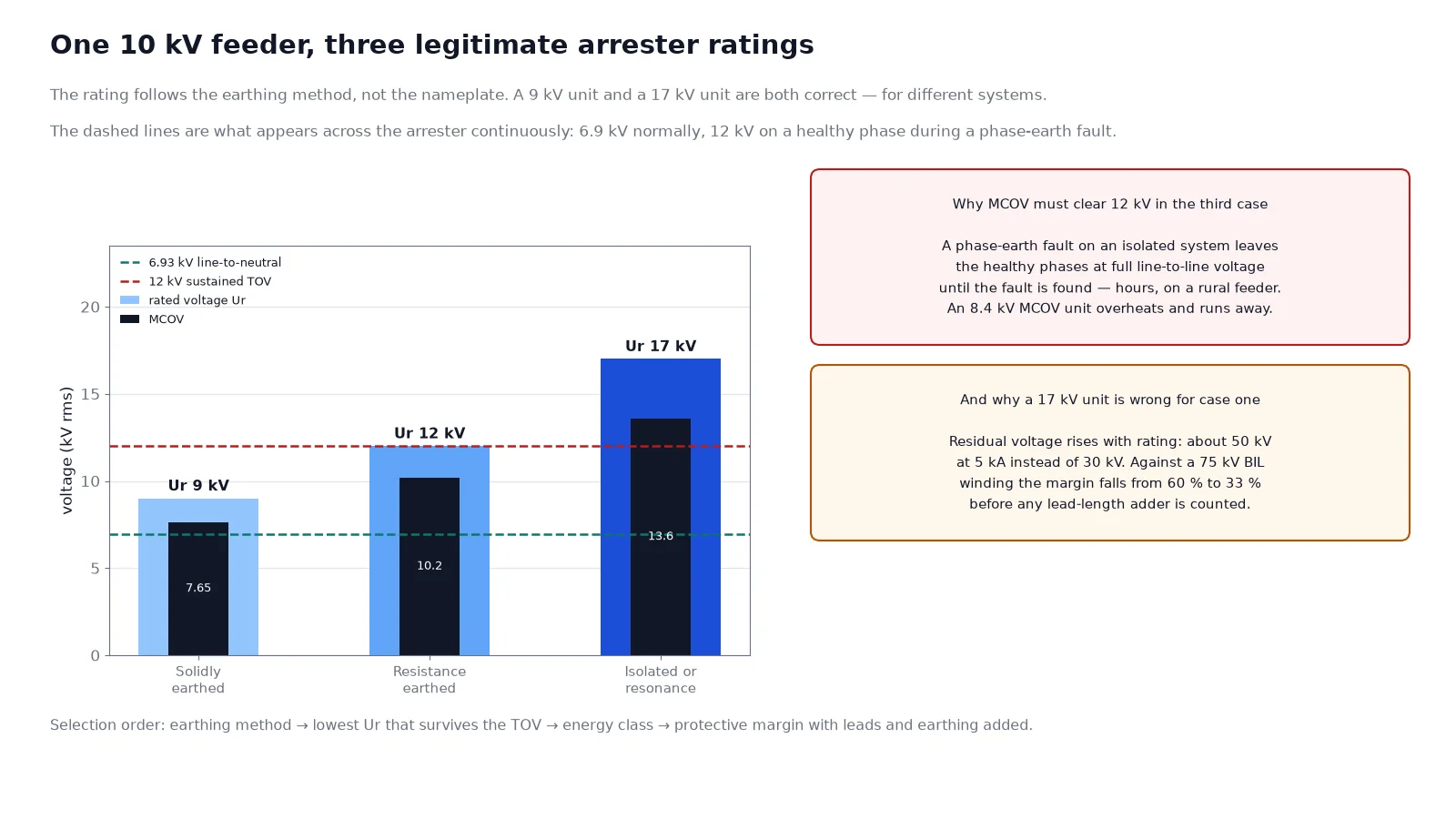
This is the step where most specification errors originate. The arrester has to survive the highest power-frequency voltage that can appear across its terminals for the duration of a fault, and that voltage is set by the earthing method, not by the 10 kV nameplate.
On a solidly earthed system, a single-phase fault raises the healthy-phase voltage only slightly above normal. On an isolated or resonance-earthed system, the same fault lifts the healthy phases to full line-to-line voltage — 12 kV instead of 6.9 kV — and it stays there until the fault is cleared, which on a rural feeder can be hours.
| Neutral treatment on the 10 kV side |
Voltage on healthy phase during a phase-earth fault |
Typical arrester Ur |
Typical MCOV |
| Solidly earthed |
≈ 1.0–1.1 × line-to-neutral (7–7.6 kV) |
9 kV |
7.65 kV |
| Earthing transformer or low resistance |
≈ 1.2–1.4 × line-to-neutral (8.3–9.7 kV) |
12 kV |
10.2 kV |
| Isolated, or resonance (Petersen coil) earthed |
Full line-to-line, up to 12 kV, sustained |
15–17 kV |
12.7–13.6 kV |
The practical rule for a solidly earthed system is Ur ≥ 1.25 × Um / √3, which for Um = 12 kV gives 8.66 kV and therefore the 9 kV standard rating. For a system that can sustain line-to-line voltage on a healthy phase, the continuous voltage rating must be at or above 12 kV, which pushes the selection to the 17 kV unit — the familiar 17/50 designation on distribution arresters sold into 10 kV networks.
If you do not know the earthing method, you do not have enough information to buy an arrester. The neutral grounding methods comparison covers how to identify it from the substation single-line diagram and from the transformer winding connections.
The four ratings that must line up
Once the earthing class is fixed, four numbers need to be consistent with each other. A datasheet that quotes only one of them is not usable for selection.
| Rating |
What it means |
How to check it |
| Rated voltage Ur (IEC) / duty-cycle rating |
Reference voltage for every other characteristic; the arrester must withstand it for 10 s |
Ur ≥ highest expected TOV for its duration; Ur/MCOV is typically 1.18–1.25 for distribution class |
| MCOV (IEEE) or continuous operating voltage |
Highest rms voltage that can be applied indefinitely without thermal runaway |
MCOV ≥ Um / √3 × 1.05 unbalance and tolerance allowance |
| TOV capability |
Time the arrester survives at a given multiple of Ur |
Compare the TOV curve against the actual clearing time, not against a generic “10 s” claim |
| Residual voltage at nominal discharge current |
The clamping level the equipment sees |
Must leave at least a 20% margin below the transformer BIL, after lead-length adder |
The interaction between the first two is where oversizing creeps in. Buying a larger arrester looks like buying safety, but residual voltage rises with the rating, so the protective margin falls. A 17 kV arrester on a solidly earthed 10 kV bus will survive almost anything and may fail to protect a 75 kV BIL transformer once installation adders are counted.
Energy class and nominal discharge current
IEC 60099-4 grades arresters by line discharge class, from class 1 to class 5, tested against a defined long-duration current impulse. IEEE C62.11 uses duty classes: distribution, intermediate, station and transmission line. For a 10 kV distribution feeder the distribution class is normal; the choice inside that class is the nominal discharge current.
| Nominal discharge current |
Typical use at 10 kV |
Note |
| 5 kA |
Short feeders, low keraunic level, arrester close to the protected equipment |
Lowest residual voltage for a given rating; cheapest |
| 10 kA |
Standard choice for pole-mounted transformers and cable risers in high-lightning regions |
Most common export specification at this voltage level |
| 20 kA |
Exposed ridge lines, long overhead runs, arrester at a cable transition with no upstream protection |
Higher energy capability, larger housing, higher residual voltage |
Two related numbers belong on the same datasheet. The pressure relief rating — often 20 kA or 40 kA at distribution level — defines the fault current the housing can interrupt if the blocks fail, which is what keeps a failed arrester from becoming a busbar fault. The creepage distance, normally expressed in millimetres per kV of Um, must suit the pollution level: roughly 20 mm/kV for light, 25 mm/kV for medium and 31 mm/kV for heavy pollution, which at Um 12 kV means 240 mm, 300 mm and 372 mm respectively.
Insulation coordination: the margin has to survive the wiring
Protective margin is calculated, not assumed. The conventional requirement is that the protected equipment’s impulse withstand exceeds the arrester’s residual voltage by at least 20%, and IEC 60071-2 expresses the same idea as a protective ratio of 1.20 for lightning impulse and 1.15 for switching impulse.
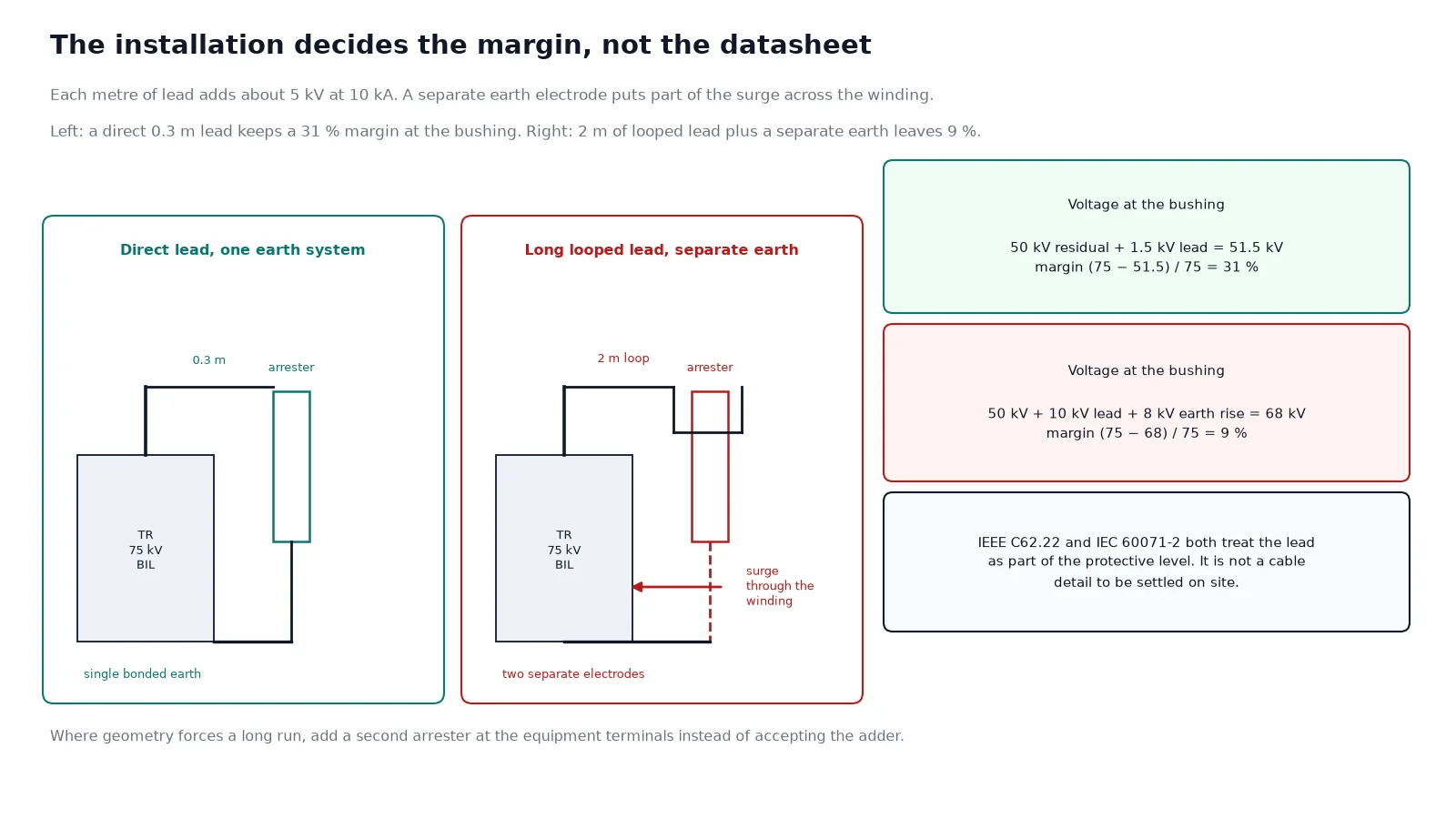
Run the numbers for a 12 kV class transformer with a 75 kV BIL and a 17 kV arrester discharging 5 kA at 50 kV residual voltage:
- Bare margin: (75 − 50) / 75 = 33%, comfortable.
- Add 1 m of connecting lead from arrester to bushing at roughly 5 kV per metre during a 10 kA surge: the voltage at the bushing becomes about 55 kV and the margin falls to 27%.
- Add a second metre routed in a loop, plus a separate earth path of a few metres: the effective voltage at the winding can approach 60 kV, and the margin is 20% — the limit, with nothing left for ageing.
That arithmetic explains why two installations with identical hardware behave completely differently. The BIL and insulation coordination guide works through the level selection itself, including altitude and pollution corrections.
Where the arrester goes on a distribution feeder
Position matters as much as rating. The four locations that carry most of the benefit on a 10 kV overhead system are:
- Transformer HV terminals. Three arresters, one per phase, mounted on the tank or on a bracket directly below the bushings. This is the non-negotiable one.
- The open point of a radial feeder. A feeder left open at a sectionalising point sees travelling waves reflect at the open end and roughly double in amplitude. An arrester at the open point limits that reflection.
- Overhead-to-underground transitions. A cable has a surge impedance an order of magnitude lower than an overhead line, so the wave that enters the cable is reduced but the wave that reflects back at the transition is not. Arresters on the overhead side protect the cable termination.
- The LV side of the transformer where the LV network is also overhead. Lightning on the LV service drop arrives at the secondary winding from the load side, and the HV arresters cannot see it.
Two arresters instead of three is a false economy on a three-phase transformer. On a solidly earthed four-wire system the phase-to-phase voltage is bounded and some standards permit two, but a transformer with two protected phases and one unprotected phase has one winding that will eventually fail. The saving is a fraction of the transformer price on a pole-mounted unit and a rounding error on anything larger — see the pole-mounted and pad-mounted comparison for how the mounting style changes the exposure.
Installation details that decide the outcome
Three installation errors account for most arrester-related transformer failures, and none of them appear on a datasheet.
Lead length and routing
Every additional metre of conductor between the arrester terminal and the equipment adds inductively generated voltage during the surge. Short, straight, direct leads are worth more than an upgrade in arrester class. Where the geometry forces a long run, mount a second arrester at the equipment terminals rather than accept the adder.
Separate earth electrodes
If the arrester has its own earth electrode and the transformer tank has another, the surge current flowing down the arrester lead raises the potential of the arrester earth above the tank earth. The difference appears across the transformer winding, and the winding carries part of the surge. Bond the arrester earth, the tank earth and the LV neutral earth to a single electrode system, and keep the resistance at or below 10 Ω for a distribution installation.
Mounting orientation and clearance
Polymer-housed arresters are usually mounted vertically, phase-up, with the earth terminal at the bottom. Horizontal mounting is acceptable for many designs but changes the pollution performance, because rain no longer washes the sheds. Keep the arrester a shed-length away from adjacent metalwork so that the voltage distribution across the housing is not distorted by a nearby earthed plane.
An arrester protects the terminals it is bolted to. Everything else it protects only by calculation.
Commissioning and condition checks
The pre-energisation checks are simple, and skipping them is common:
- Measure insulation resistance of each arrester from terminal to earth with a 2.5 kV or 5 kV tester. A very low reading means moisture ingress or a failed block.
- Confirm the earth connection resistance against the design value, and confirm the bond to the tank and the LV neutral is present and tight.
- Check that the counter, where fitted, reads zero and that its earth return is intact.
- Verify the rating on the nameplate against the drawing. Mismatched arresters in a set of three are found more often than expected on retrofits.
In service, the economical checks are leakage current measurement and infrared scanning. A resistive leakage current that has risen significantly compared with the commissioning value indicates ageing of the blocks; a hot arrester body under normal voltage means it is already conducting more than it should. The wider sequence of factory inspection is covered in the power transformer quality inspection process, and the site sequence in the pre-commissioning checklist.
Application environments change the maintenance weight. Coastal and tropical sites with high salt deposition need shed cleaning on a defined interval, and the pollution level assumed at design must be re-checked if an industrial plant is built nearby. Two application notes cover the extremes: transformers for mining, where conductive dust is the dominant stress, and metro and tunnel substations, where the arrester sits in a confined space with restricted clearances and no rain washing.
Common selection mistakes
| Mistake |
What happens |
Correction |
| Specifying Ur equal to the nominal system voltage (10 kV) on an isolated system |
Continuous line-to-line voltage on healthy phases drives thermal runaway within months |
Use the earthing method, not the nominal voltage; 17 kV for isolated or resonance earthed |
| Choosing the highest rating available “for safety” |
Residual voltage rises, protective margin disappears, transformer is unprotected in practice |
Take the lowest rating that survives the TOV, then verify the margin |
| Comparing residual voltages measured at different discharge currents |
Apparent 15–20% difference between two equivalent units |
Compare at the same current, normally the nominal discharge current |
| Separate earth electrode for the arrester |
Part of the surge is applied across the transformer winding |
Single bonded earth system, ≤ 10 Ω |
| Ignoring lead length in the margin calculation |
Calculated margin passes, installed margin fails |
Add roughly 5 kV per metre and re-check |
Frequently asked questions
What size surge arrester do I need for a 10kV system?
On a solidly earthed 10 kV (Um 12 kV) system the usual choice is a 9 kV rated arrester with 7.65 kV MCOV. On an isolated or resonance-earthed system the standard choice is 15–17 kV rated with 12.7–13.6 kV MCOV, because a single-phase fault raises the healthy-phase voltage to line-to-line. The earthing method, not the nominal voltage, is the deciding input.
What does 17/50 mean on a distribution arrester?
The first figure is the rated voltage in kV rms and the second is the maximum residual voltage in kV at the nominal discharge current, usually 5 kA with an 8/20 µs wave. A 17/50 arrester therefore clamps a 5 kA surge at about 50 kV, which is the number that has to be compared with the protected equipment’s BIL.
Can I use one arrester for three phases?
No. A single arrester protects one phase to earth. Three-phase protection needs one arrester per phase at the equipment terminals, plus an additional unit on the LV side where the low-voltage network is overhead.
How long do metal-oxide arresters last?
There is no fixed service life. The blocks age in proportion to the energy they absorb and to the continuous voltage stress relative to MCOV. A correctly rated unit on a clean system commonly runs fifteen to twenty years; an overstressed or moisture-contaminated unit can fail in a single season. Leakage current trending is the practical indicator.
Does an arrester protect against switching surges as well as lightning?
Yes, but the margin basis is different. Switching impulse withstand is lower than lightning impulse withstand, while the arrester’s switching residual voltage is also lower, so the ratio usually remains acceptable. The case that needs checking is vacuum circuit breaker restriking on a small inductive load, where multiple restrikes produce steep-fronted surges that the arrester may not clamp quickly enough.
Why did my arrester fail in the first rainy season?
The usual causes, in order of frequency, are a rating selected for the wrong earthing class, moisture ingress through a damaged housing or a poor seal at the earth end, and pollution-induced surface flashover that leaves a conductive track. None of these is a lightning problem, and all three are visible during commissioning or the first infrared scan.
The takeaway
Surge arrester selection at 10 kV is a four-step calculation disguised as a catalogue lookup: establish the earthing method, take the lowest rated voltage that survives the resulting temporary overvoltage, confirm the energy class against the exposure, then verify the protective margin including lead length and earth bonding. The installation details are not secondary — a correctly specified arrester with long leads and a separate earth protects less than a modestly rated one bolted directly to the bushings.
If you are specifying arresters together with distribution transformers, send us the single-line diagram and the earthing arrangement; we will confirm the rating against the transformer BIL and the site pollution level before the order is placed.